Image processing method and device

A technology in images and images, applied in the field of image processing methods and equipment, and can solve problems such as low image quality

Active Publication Date: 2015-02-18
HUAWEI TECH CO LTD
View PDF3 Cites 26 Cited by
  • Summary
  • Abstract
  • Description
  • Claims
  • Application Information

AI Technical Summary

Problems solved by technology

[0004] In view of this, an embodiment of the present invention provides an image processing method and device for solving the current problem of low quality of collected images

Method used


Image

  • Image processing method and device
  • Image processing method and device
  • Image processing method and device

Examples


Embodiment 1

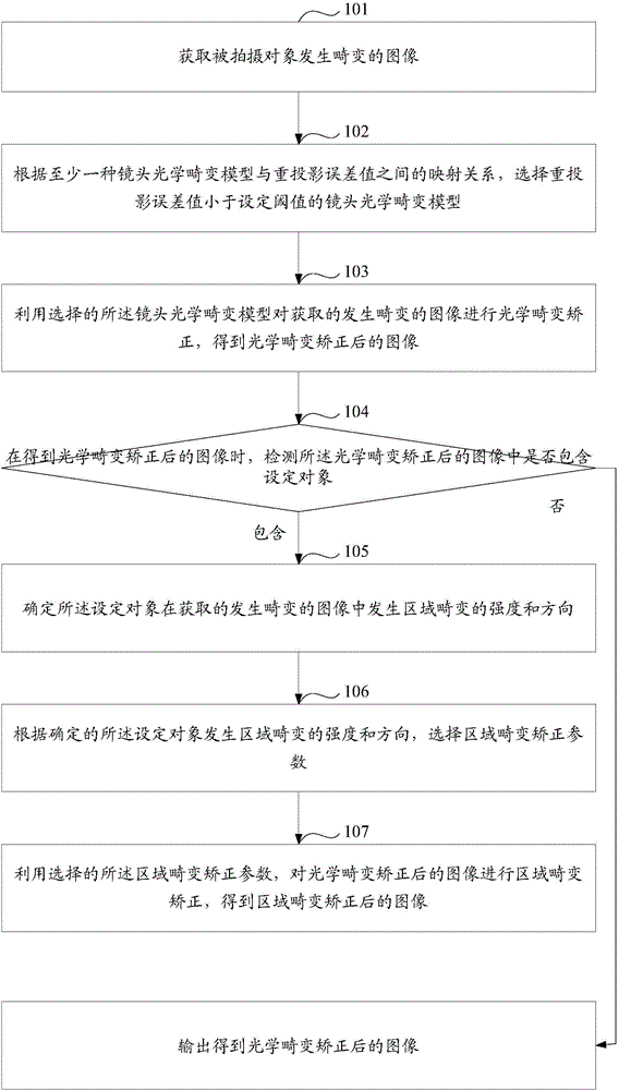
[0182] Such as figure 1 As shown, it is a schematic flowchart of an image processing method provided in Embodiment 1 of the present invention, and the subject of execution of the method may be a terminal device. Wherein, the method includes:

[0183] Step 101: Acquire a distorted image of a subject.

[0184] In step 101, in the stage of acquiring a distorted image of the subject, the terminal device uses the imaging function of the imaging unit to map the subject to the image sensor to obtain a distorted image, and the image sensor maps the obtained distorted image Sent to the processor of the end device.

[0185] Wherein, the terminal device may be a terminal device with a camera function such as a camera, a video camera, or a mobile phone, and the imaging unit may be a lens in the terminal device.

[0186] During the process of converting the object to be photographed by the lens into an image, due to the optical reasons of lens imaging and / or the spatial distance between...

Embodiment 2

[0329] Such as Figure 4 As shown, it is a schematic structural diagram of an image processing device provided by Embodiment 2 of the present invention. The image processing device has the functions of Embodiment 1 of the present invention. The function of the correction device can be realized by a general computer. The image processing device entity includes an imaging device 31 , an image sensor 32 , and a processor 33 . Wherein, the image sensor 32 and the processor 33 are connected through a bus 34 .

[0330] The imaging device 31 is configured to map the object to be photographed onto an image sensor 32;

[0331] The image sensor 32 is configured to acquire a distorted image;

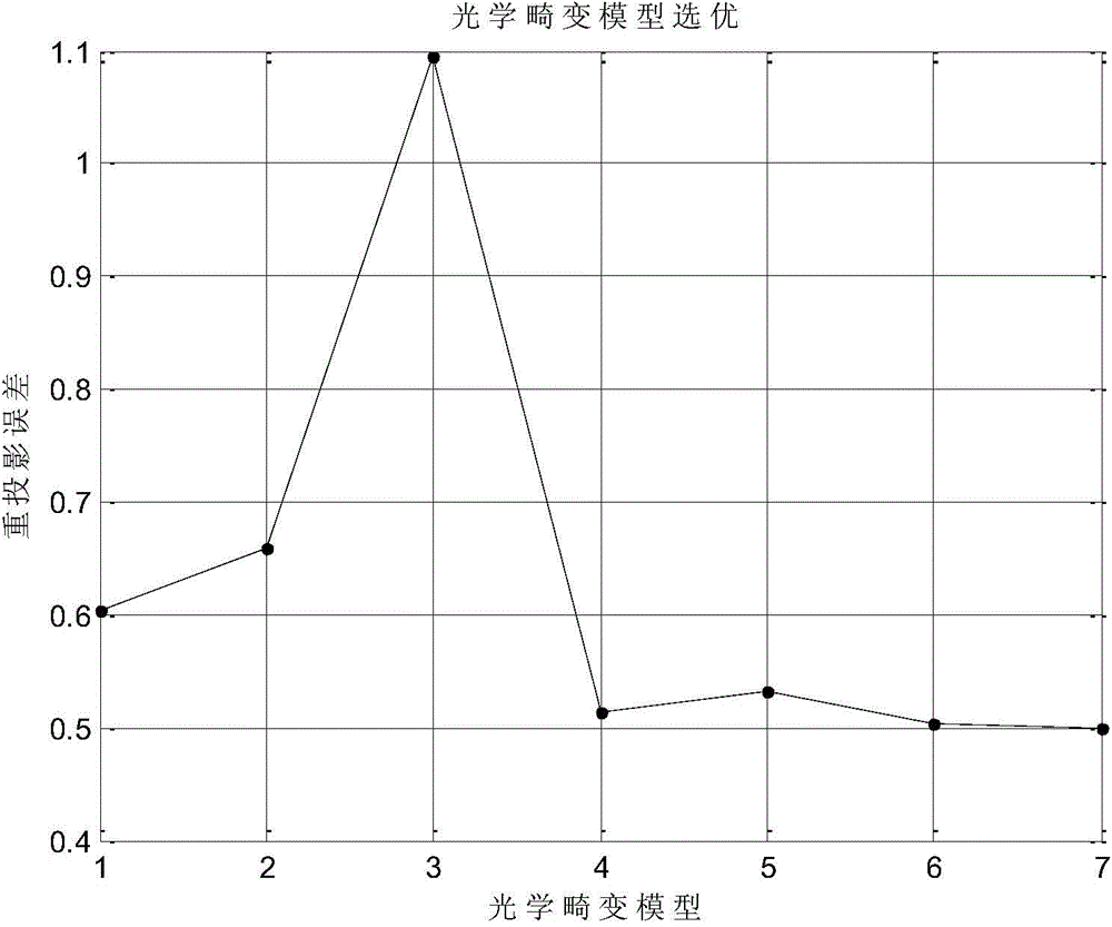
[0332] The processor 33 is configured to select a lens optical distortion model whose reprojection error value is less than a set threshold according to the mapping relationship between at least one set of lens optical distortion models and reprojection error values, wherein the lens optical di...

Embodiment 3

[0391] Such as Figure 5 As shown, it is a schematic structural diagram of an image processing device provided in Embodiment 3 of the present invention. The image processing device includes: an acquisition module 41, a selection module 42, and a processing module 43, wherein:

[0392] An acquisition module 41, configured to acquire a distorted image of the subject;

[0393] The selection module 42 is configured to select a lens optical distortion model whose reprojection error value is smaller than a set threshold according to the mapping relationship between at least one set of lens optical distortion models and the reprojection error value, wherein the lens optical distortion model includes optical Distortion type, distortion order and distortion coefficient, the reprojection error value is used to represent the difference between the theoretical distorted image coordinate value of the calibration object and the actual distorted image coordinate value of the calibration obje...


PUM


Abstract

The invention discloses an image processing method and device. The method comprises: a distorted image of a captured object is obtained; according to a mapping relation between optical distortion models of at least one set of lenses and reprojection error values, an optical distortion model with a reprojection error value smaller than a set threshold is selected and includes an optical distortion type, a distortion order and a distortion coefficient, the reprojection error value being used for representing the differences between theoretical distorted image coordinates and real distorted image coordinates of any marked object; the model is used for optical distortion correction of an obtained distorted image to obtain an image subjected to optical distortion correction. The method effectively eliminates optical distortion induced by optical imaging theories of an imaging device during the process of obtaining the image of the captured object, and improves the quality of the captured image.

Description

technical field [0001] The present invention relates to the technical field of wireless communication, in particular to an image processing method and device. Background technique [0002] With the rapid development of smart phones and mobile Internet, terminal devices (such as video cameras, cameras, etc.) have become very important components of smart phones as an interface connecting the real world and the virtual network world. Thousands of people record new things related to or irrelevant to themselves through the camera function or camera function of their smartphones every day. [0003] Among the large number of new things recorded by people, face images account for a considerable proportion. However, in the process of converting human facial features into human face images by using optical principles, terminal equipment is prone to optical distortion, resulting in distortion of facial features in the obtained human face images. For example: the barrel distortion th...

Claims


Application Information

Patent Timeline
Patent Type & Authority Applications(China)
IPC IPC(8): A99Z99/00
CPCH04N5/21H04N17/00H04N25/61G06T5/006G06T7/30G06T5/001G06T5/002
Inventor 陈刚唐忠伟罗巍
Owner HUAWEI TECH CO LTD
Why Eureka
Try Eureka