Machine and needle bar
A sewing machine and needle bar technology, which is applied in the field of industrial use, can solve the problems of unstable operation of the needle bar, increase the manufacturing cost of the sewing machine, etc., and achieve the effects of simple structure, improved yield and reduced resistance.
- Summary
- Abstract
- Description
- Claims
- Application Information
AI Technical Summary
Problems solved by technology
Method used
Image
Examples
no. 1 Embodiment approach
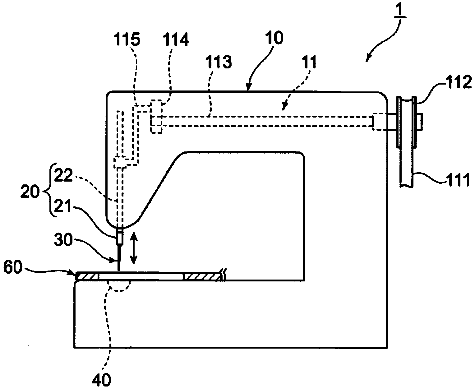
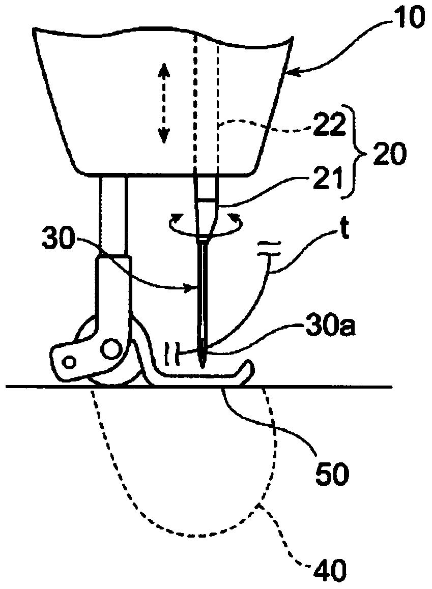
[0042] First, refer to Figure 1 to Figure 4A first embodiment of the sewing machine 1 according to the present invention will be described.
[0043] This sewing machine 1 consists of figure 1 , figure 2 parts shown. It includes a sewing machine body 10 for accommodating various parts, a needle bar 20 arranged on the sewing machine body, a sewing needle 30 fixed on the needle bar 20, a kettle 40 for receiving the sewing needle 30, a cloth pressing plate 50 for pressing the cloth, and a feeding material for transporting the cloth device 60. The needle bar 20 and the sewing needle 30 are reciprocated up and down by a driving motor whose illustration is omitted. Then, while the processed objects such as synthetic leather, leather products, and cloth are fed manually or automatically by the feeding device 60, the needle bar 20 and the seam reciprocate up and down relative to the kettle 40, so that the upper thread t of the sewing needle 30 passes through The lower thread (no...
no. 2 Embodiment approach
[0051] Below, will refer to Figure 5 to Figure 10 , and a second embodiment of the sewing machine according to the present invention will be described.
[0052] In addition, in the following content, only the structure different from the above-mentioned embodiment will be explained, and the description of the same structure will be omitted and the same code|symbol will be attached. In addition, regarding the vertical reciprocating movement of the needle bar 21 of the sewing machine, the highest position reached by the needle bar 20 is called the upper dead point, and the lowest position reached by the needle bar 20 is called the bottom dead point.
[0053] Such as Figure 5 ~ Figure 8 As shown, in this embodiment, the air ejection portion 70 is provided near the rear of the needle bar 20 , and the air receiving portion 25 is provided on the rear side of the front end side of the needle bar 21 of the needle bar 20 . The air receiving portion 25 receives the air ejected from ...
no. 3 Embodiment approach
[0068] Below, will refer to Figure 11 ~ Figure 13 , and a third embodiment of the sewing machine according to the present invention will be described. In addition, in the following content, only the structure different from the above-mentioned embodiment will be explained, and the description of the same structure will be omitted and the same code|symbol will be attached.
[0069] In this embodiment, if Figure 11 As shown, a guide portion 80 is provided near the right side of the needle bar 20 , and a protruding portion 26 is provided on the side of the right circumference of the needle bar 21 on the front end side of the needle bar 20 . When the needle bar 20 moves downward, the front-end side needle bar 21 rotates around the axis G of the up and down reciprocating motion sequentially around the axis G with the protruding part 26 guided by the guide part 80. At , the specified basic orientation is restored.
[0070] Such as Figure 11 As shown, the aforementioned protru...
PUM
 Abstract
Description
Claims
Application Information
 - R&D
- Intellectual Property
- Life Sciences
- Materials
- Tech Scout
- Unparalleled Data Quality
- Higher Quality Content
- 60% Fewer Hallucinations
Browse by: Latest US Patents, China's latest patents, Technical Efficacy Thesaurus, Application Domain, Technology Topic, Popular Technical Reports.
© 2025 PatSnap. All rights reserved.Legal|Privacy policy|Modern Slavery Act Transparency Statement|Sitemap|About US| Contact US: help@patsnap.com


