Heat exchangers for refrigerant circuits

A technology of heat exchangers and refrigerants, applied in heat exchange equipment, refrigerators, refrigeration components, etc., can solve the problems of air-conditioning system output drop, heat exchange surface icing, reduction, etc., to increase efficiency, reduce fuel consumption, The effect of increasing the driving distance

Active Publication Date: 2017-03-01
HANON SYST
View PDF9 Cites 0 Cited by
  • Summary
  • Abstract
  • Description
  • Claims
  • Application Information

AI Technical Summary

Problems solved by technology

[0009] Due to the lower pressure stage, the refrigerant density when operating in heat pump mode is greatly reduced on the low pressure side of the refrigerant circuit, therefore, the additional flow pressure loss has a significant adverse effect on the performance and efficiency of the heat pump system
[0010] In addition, at a temperature below 0°C, when operating in a heat pump mode with the help of a refrigerant circuit and ambient air as a heat source, there is a risk of freezing the heat exchange surface of the heat exchanger operating as an evaporator.
But the proposed method caused a huge drop in the output of the air-conditioning system

Method used


Image

  • Heat exchangers for refrigerant circuits
  • Heat exchangers for refrigerant circuits
  • Heat exchangers for refrigerant circuits

Examples


Embodiment Construction

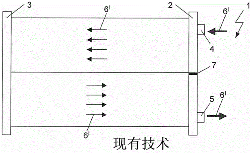
[0069] exist figure 1 In Fig. 1 , a heat exchanger 1 having a 2-pass configuration as a conventional condenser / gas cooler in cooling device mode is shown. However, the heat exchanger 1 is preferably a component of a refrigerant circuit of an automotive air-conditioning system (not shown).

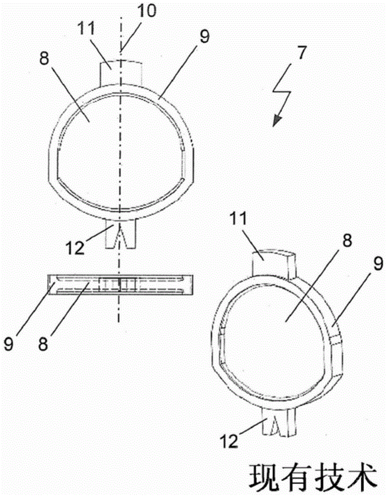
[0070] The gaseous refrigerant compressed by the refrigerant compressor flows into the first header 2 of the heat exchanger 1 through the first refrigerant inlet and outlet 4 due to its high temperature. The first header 2 comprises static separation elements 7 which divide the header 2 into mutually independent and mutually closed regions. Such static separating elements 7 are formed, for example, from sheet metal.

[0071] In the upper region, the gaseous refrigerant introduced into the first header 2 is evenly distributed to the plurality of flow paths of the first channel. Flow paths are identified with solid arrows. The refrigerant flows from the first header 2 to the second header...


PUM


Abstract

The invention relates to a bi-directional heat exchanger (1) for a refrigerant circuit of an automobile air-conditioning system. The air-conditioning system is formed to perform combined operation of the cooling device mode and the heat pump mode, the heat exchanger (1) is formed in multiple paths, and the flow direction of the refrigerant is different depending on the operation mode. The first heat exchanger (1) formed in multiple paths includes headers (2, 3), flow paths respectively assigned to the channels and the internal volume space of at least one header (2, 3) is divided into mutually independent devices in the area. The first channel of the heat exchanger (1) is formed by a larger flow cross section and larger heat exchange surface than the last channel. In the second heat exchanger (1), a connection block (28) for connecting the refrigerant pipeline (27) to the refrigerant inlet and outlet (4) is formed, between the header (2) and the connection block (28) , a short-circuit line (29) formed as an additional fluid connection with the refrigerant inlet and outlet (4) is arranged. Furthermore, the invention relates to a device for dividing the inner volume of the headers (2, 3) of the heat exchanger (1). Inside the header (2, 3), at least one movable separation element (13, 13') is arranged, the movable separation element (13, 13') is formed according to the principle of differential pressure, and according to its (2, 3) The internal arrangement and the pressure difference applied thereto open or close the opening.

Description

technical field [0001] The invention relates to a heat exchanger for a refrigerant circuit of an automotive air conditioning system. Such heat exchangers include header pipes formed to enable multi-pass and bidirectional through-flow. The air conditioning system is configured to operate in a combination of a cooling mode and a heating mode. The flow direction of the refrigerant inside the heat exchanger varies depending on the operation mode. [0002] In addition, the invention relates to a device for dividing the internal volume of the headers of the heat exchanger and diverting the flow of fluid in the headers of the heat exchanger. Background technique [0003] Conventional air conditioning systems in automobiles consist of a combined cooling device and heat pump system. The heat exchanger is configured to release heat from the refrigerant to ambient air as a condenser in chiller mode and to absorb heat from ambient air as an evaporator in heat pump mode. [0004] Acc...

Claims


Application Information

Patent Timeline
Patent Type & Authority Patents(China)
IPC IPC(8): F28D1/04F28D1/053F28F27/02F28F9/02
CPCF25B39/00F28F9/0212F28F9/028F28F27/02F28D1/05375F28D2021/0084F28D2021/0085F28D2021/0068F28F2250/06F25B49/02F28D1/04F28D1/053F28F9/02B60H1/00342F25B30/02F28D21/00
Inventor 彼得·海尔托比亚斯·哈斯马克·格拉夫米兰·莫拉韦克伊里·多布纳扬·格雷古斯-科拉尔
Owner HANON SYST
Why Eureka
Try Eureka