An Injection Mold for Automatic Shearing of Disc Gate Agglomerate in Mold

An injection mold and gate technology, applied in the field of injection mold design and manufacturing, can solve the problems of difficult removal of brittle and hard materials, complex design and manufacturing assembly, and difficulty in cutting the gate condensate, and achieves simple peripheral control, simple structure, and mold. compact effect

Inactive Publication Date: 2016-11-09
DALIAN UNIV OF TECH
View PDF6 Cites 0 Cited by
  • Summary
  • Abstract
  • Description
  • Claims
  • Application Information

AI Technical Summary

Problems solved by technology

Cutting after mold opening is easy to pull the product, making it difficult to cut the gate aggregate, making it more difficult to cut brittle and hard materials, and the product is easily damaged
Before the mold is opened, the gate aggregate is mainly punched by the in-mold cutter, but this requires a room in the mold along the punching direction to cut off the gate aggregate. For this reason, the corresponding mold must be designed and manufactured. The mechanism operates synchronously with the cutter, but the design, manufacture and assembly of this mechanism are more complicated and require precise control. It is mainly used for products with large batches, such as CDs and DVDs; for general disc-shaped gate molding products, There is an urgent need for an economical and reliable in-mold gate device

Method used


Image

  • An Injection Mold for Automatic Shearing of Disc Gate Agglomerate in Mold
  • An Injection Mold for Automatic Shearing of Disc Gate Agglomerate in Mold
  • An Injection Mold for Automatic Shearing of Disc Gate Agglomerate in Mold

Examples


Embodiment Construction

[0014] The present invention will be described in detail below in conjunction with the accompanying drawings and specific embodiments.

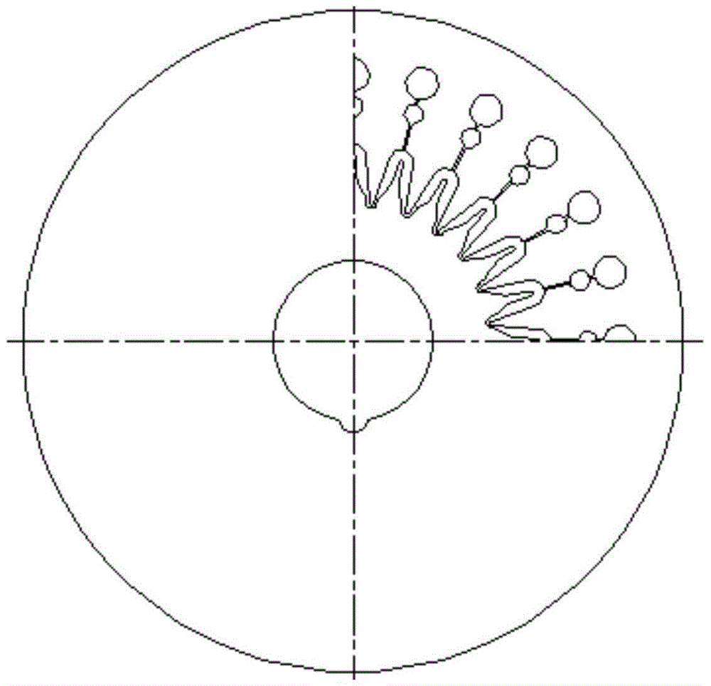
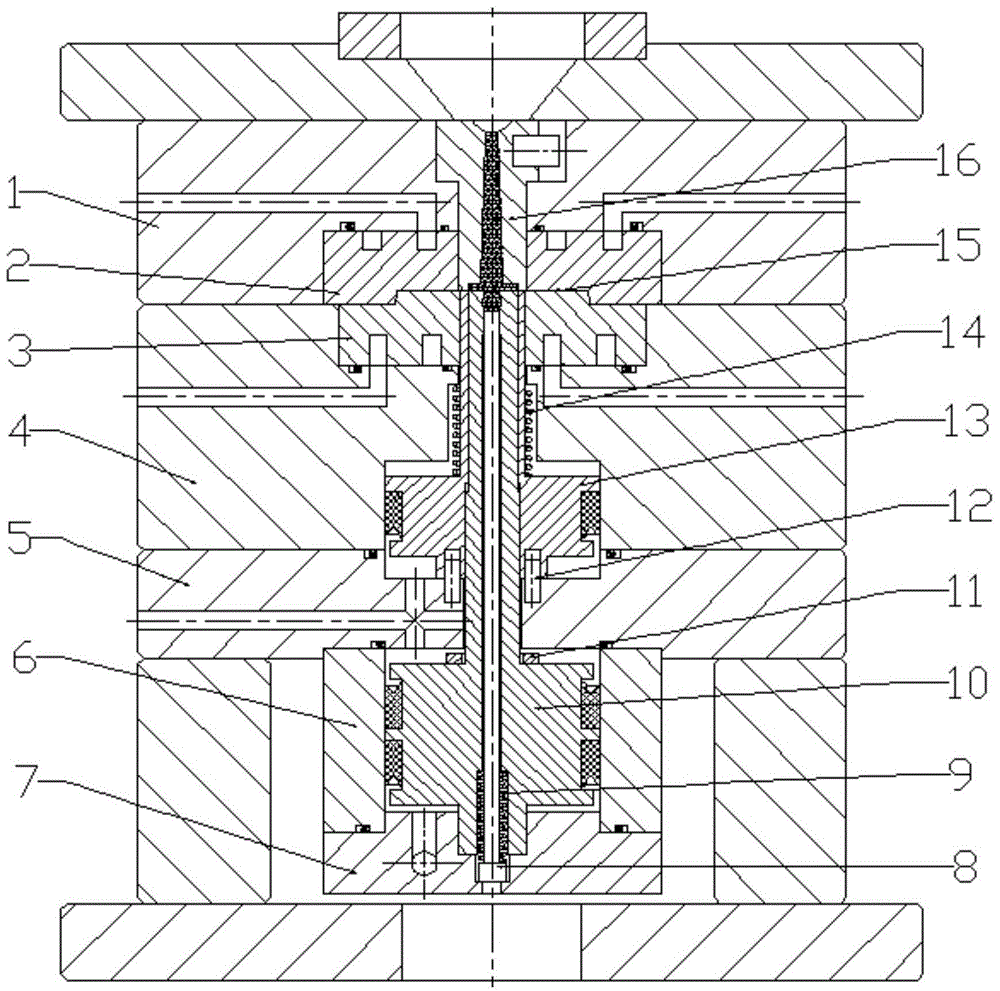
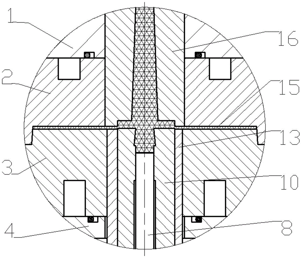
[0015] Figure 1 to Figure 3 It is a specific implementation case of the patent of the present invention. The molded product is a disc-shaped microfluidic chip, such as figure 1 shown. Microstructure arrays are designed on the chip, such as figure 1 In the partial structure shown in the figure, the central hole is a special-shaped hole, and the forming gate adopts a disc gate with a smaller cross-sectional area. Mold assembly relationship such as figure 2 As shown, the local details of the gating system can be found in image 3 .

[0016] The pouring system and cavity are jointly formed by the fixed mold insert 2, the movable mold insert 3, the sprue sleeve 16, the gate punch 10, the push tube 13 and the center push rod 8, wherein the sprue sleeve 16 and the gate punch The axial gap of 10 forms a disc-shaped gate, and the thickness of...


PUM

PropertyMeasurementUnit
thicknessaaaaaaaaaa

Abstract

The invention discloses an injection mold automatically shearing a disk-shaped sprue coagulation material in the mold, and belongs to the field of injection mold design and manufacture, wherein the injection mold is mainly composed of a sprue bushing, a fixed die insert block, a moving die insert block, a sprue punch, a push tube, a center push rod, a spacing ring, a support plate, a cylinder assembly and the like. An injection-molded disk-shaped sprue is formed by matching the sprue bushing and the sprue punch, the thickness of the disk-shaped sprue is generally 0.1-0.5 mm, and moreover, the depth of a groove matched with the sprue punch and designed on the end face of the sprue bushing is 1-5 mm. After injection pressure maintaining is finished, the sprue punch is driven to move forward by a gas cylinder to allow the sprue coagulation material to enter the sprue bushing groove, and the two components achieve a shearing action for cutting off the sprue coagulation material. The sprue coagulation material after cutting is stayed on the sprue punch due to an action of the sprue punch internally pushing a trough, and after the mold is opened, the sprue coagulation material is pushed out by the center push rod in the sprue punch. Compared with same-kind molds, the injection mold is more compact in structure and strong in versatility; and with application of the mold for molding a product, the product quality can be ensured, and economic benefits are improved.

Description

technical field [0001] The invention belongs to the field of injection mold design and manufacture, and relates to an injection mold for automatically shearing disc-shaped gate aggregates in a mold. Background technique [0002] When using a disc gate to form a plastic product, the gate aggregate cannot be automatically separated from the product during the demoulding process, so manual or special gate aggregate cutting device is required for subsequent processing, and this gate aggregate The cutting method is easy to cause damage to the product and affect the quality of the product, and increases the amount of labor and prolongs the production cycle. For this reason, the method of automatically shearing the gate aggregate in the mold can be used to solve the above problems. [0003] The existing methods of automatically cutting the gate aggregate in the mold are mainly divided into two action modes: cutting after mold opening and cutting before mold opening. Cutting after...

Claims


Application Information

Patent Timeline
Patent Type & Authority Patents(China)
IPC IPC(8): B29C45/38
CPCB29C45/38B29C2045/384
Inventor 宋满仓于文强张志强刘莹刘冲刘军山李经民
Owner DALIAN UNIV OF TECH
Why Eureka
Try Eureka