Oil-water separation device

An oil-water separation device, oil-water separation technology, applied in the direction of grease/oily substance/floating matter removal device, water/sewage multi-stage treatment, water/sludge/sewage treatment, etc., can solve the problem of solid residues that are difficult to remove, oil, water , impurity sludge is difficult to separate and other problems, to achieve the effect of improving efficiency, avoiding clogging and improving treatment efficiency

Inactive Publication Date: 2015-02-25
MIRACLE HANGZHOU ENVIRONMENTAL TECH
View PDF5 Cites 11 Cited by
  • Summary
  • Abstract
  • Description
  • Claims
  • Application Information

AI Technical Summary

Problems solved by technology

The existing oil-water separator has the problem that oil, water, impurities, and sludge are difficult to separate. Even if the oil and water have been separated, the solid residue and sludge contained in the oil are difficult to remove.

Method used


Image

  • Oil-water separation device
  • Oil-water separation device
  • Oil-water separation device

Examples


Embodiment 1

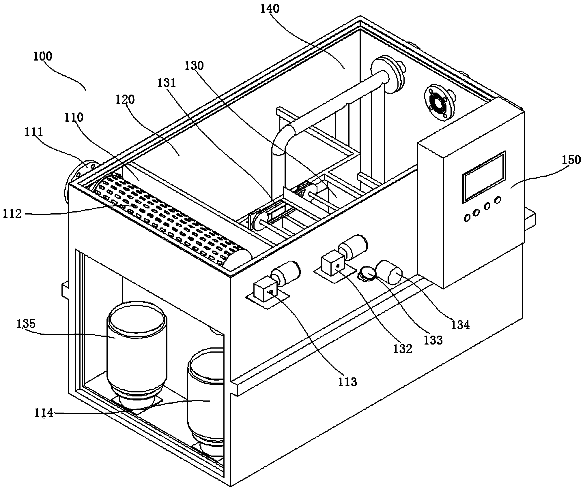
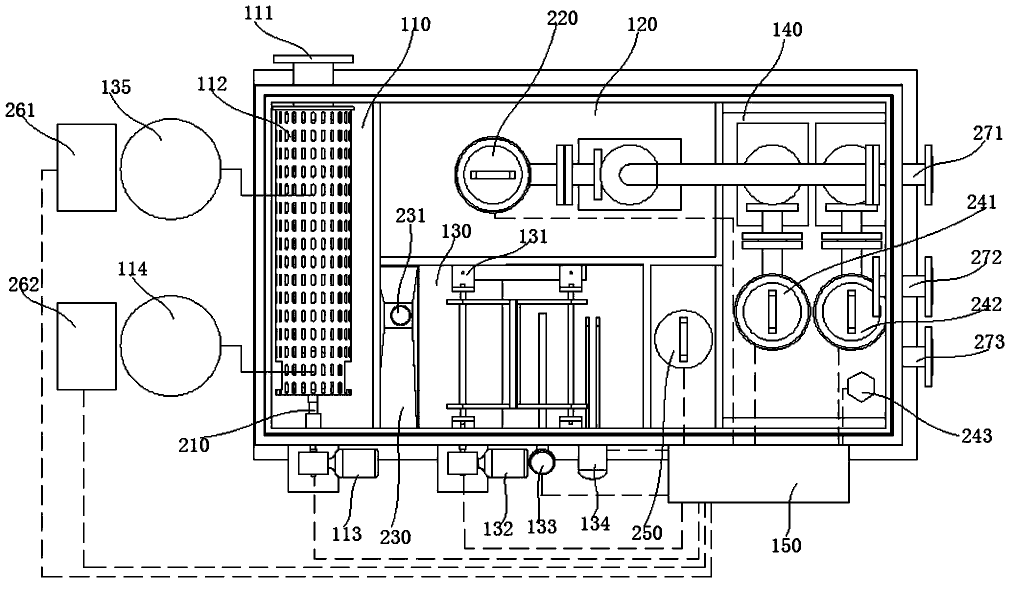
[0036] Such as figure 1 , figure 2 As shown, the oil-water separation device in this embodiment includes a device body 100. The device body 100 is provided with a water inlet 111 and a water outlet 271; the device body 100 is also provided with a slag removal chamber 110, a sedimentation chamber 120, and oil and water. Separating cavity 130 and water storage cavity 140;

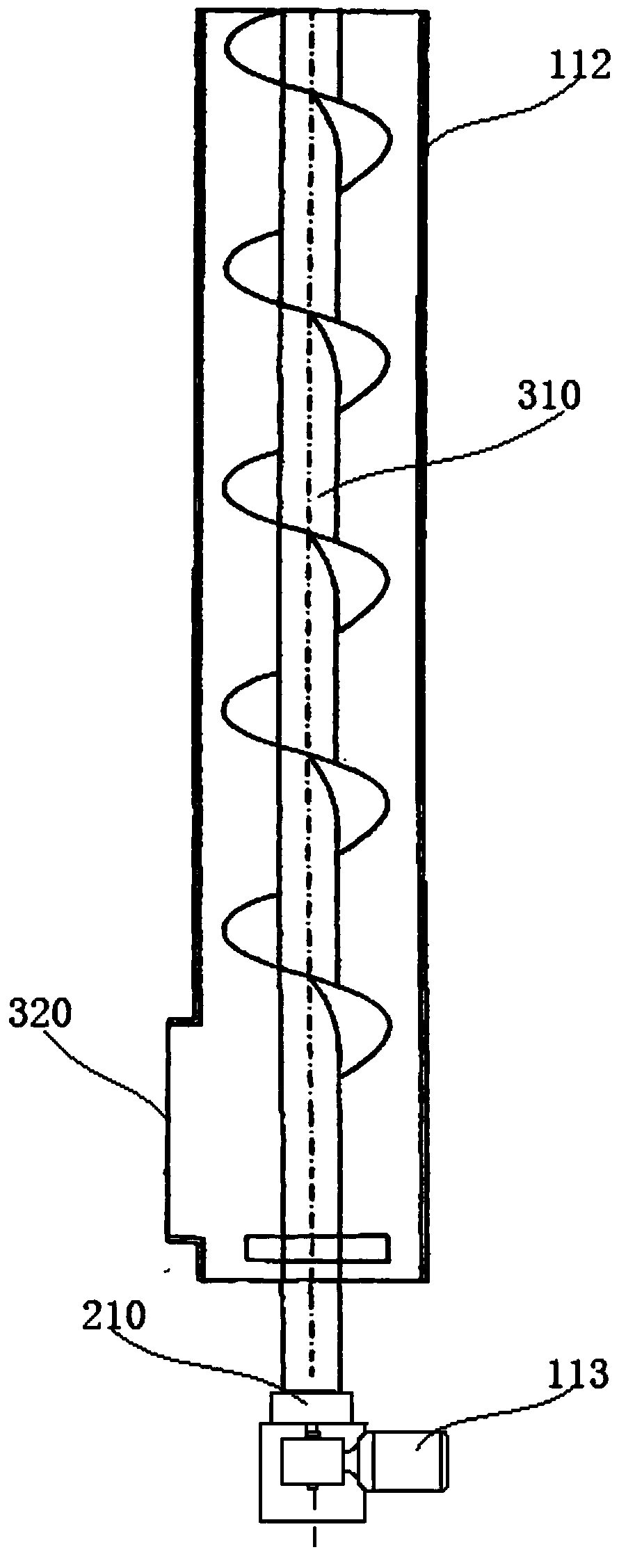
[0037] The deslagging chamber 110 is provided with a deslagging drum 112. The water inlet 111 communicates with the interior of the deslagging drum 112. The side wall of the deslagging drum 112 is structured in a grid shape; the sewage flows into the deslagging drum 112 from the water inlet 111 and flows from the deslagging drum 112. The side wall of the cylinder 112 flows out, and flows into the precipitation chamber 120 after the solid residue is removed, and flows into the oil-water separation chamber 130 after precipitation and removal of small particles in the precipitation chamber 120;

[0038] A submersibl...


PUM


Abstract

The invention relates to the technical field of sewage treatment, and particularly relates to an oil-water separation device. A water inlet and a water outlet are formed in a device body, a residue removal cavity, a precipitation cavity, an oil-water separation cavity and a water storage cavity are formed in the device body. A residue removal cylinder is arranged in the residue removal cavity, the side wall of the residue removal cylinder is mesh-shaped. Sewage flows in the residue removal cylinder from the water inlet and flows out from the side wall of the residue removal cylinder so as to remove solid residues and flow in the precipitation cavity, small particle residues are precipitated and removed in the precipitation cavity, and the water flows in the oil-water separation cavity. A chain type oil scraping machine and an oil collection tank are arranged in the oil-water separation cavity, oil separated from the sewage is led into the oil collection tank through the chain type oil scraping machine. Sewage subjected to oil-water separation through the oil-water separation cavity flows in the water storage cavity through a siphon device, a sewage lift pump is arranged in the water storage cavity and is used for pumping the sewage in the water storage cavity out of the water outlet. The oil-containing sewage can be better treated by the oil-water separation device.

Description

Technical field [0001] The invention relates to the technical field of sewage treatment, in particular to an oil-water separation device. Background technique [0002] At present, the slop produced by the catering industry contains a lot of grease, and direct discharge will cause blockage of sewer pipes, waste of resources, and pollution to the environment. At present, most of the water is filled in buckets, transported to the recycling place, and then the oil and water are separated by a simple manual separation method, and the liquid needs to be pumped. In order to improve the separation efficiency, chemical agents need to be added. The disadvantages are that the amount of water is large, and a large-capacity container is required. Therefore, the handling is labor-intensive, the transportation volume is large, the manual separation efficiency is low, the separation is not complete, and the addition of chemicals will cause secondary pollution. [0003] The oil-water separator is...

Claims


Application Information

Patent Timeline
Patent Type & Authority Applications(China)
IPC IPC(8): C02F9/02
CPCC02F9/00C02F1/001C02F1/40C02F1/52
Inventor 张建文
Owner MIRACLE HANGZHOU ENVIRONMENTAL TECH
Why Eureka
Try Eureka