
High-stable and semi-flexible supporting structure for secondary lens of space camera

A support structure and space camera technology, applied in the field of aerospace optical remote sensing cameras, can solve the problems of poor static performance, large acceleration response multiple, low stiffness, etc., achieve high stiffness and small mass, eliminate influence, and ensure stability.

Active Publication Date: 2015-02-25
BEIJING RES INST OF SPATIAL MECHANICAL & ELECTRICAL TECH
View PDF5 Cites 11 Cited by
  • Summary
  • Abstract
  • Description
  • Claims
  • Application Information

AI Technical Summary

Problems solved by technology

[0003] The traditional rigid connection structure has high rigidity and good static performance. However, due to the small damping, this structure has a large acceleration response multiple and a large force on the installation point of the secondary mirror assembly, which makes it difficult to withstand the emission vibration environment. On the contrary, the flexible connection structure, It has the characteristics of small acceleration response multiple and small force on the installation point of the secondary mirror assembly, but its stiffness is low and its static performance is poor

Method used


Image

  • High-stable and semi-flexible supporting structure for secondary lens of space camera
  • High-stable and semi-flexible supporting structure for secondary lens of space camera
  • High-stable and semi-flexible supporting structure for secondary lens of space camera

Examples


Embodiment Construction

[0020] The highly stable semi-flexible support structure for the secondary mirror of a space camera according to the present invention will be further described in detail with reference to the accompanying drawings and specific embodiments.

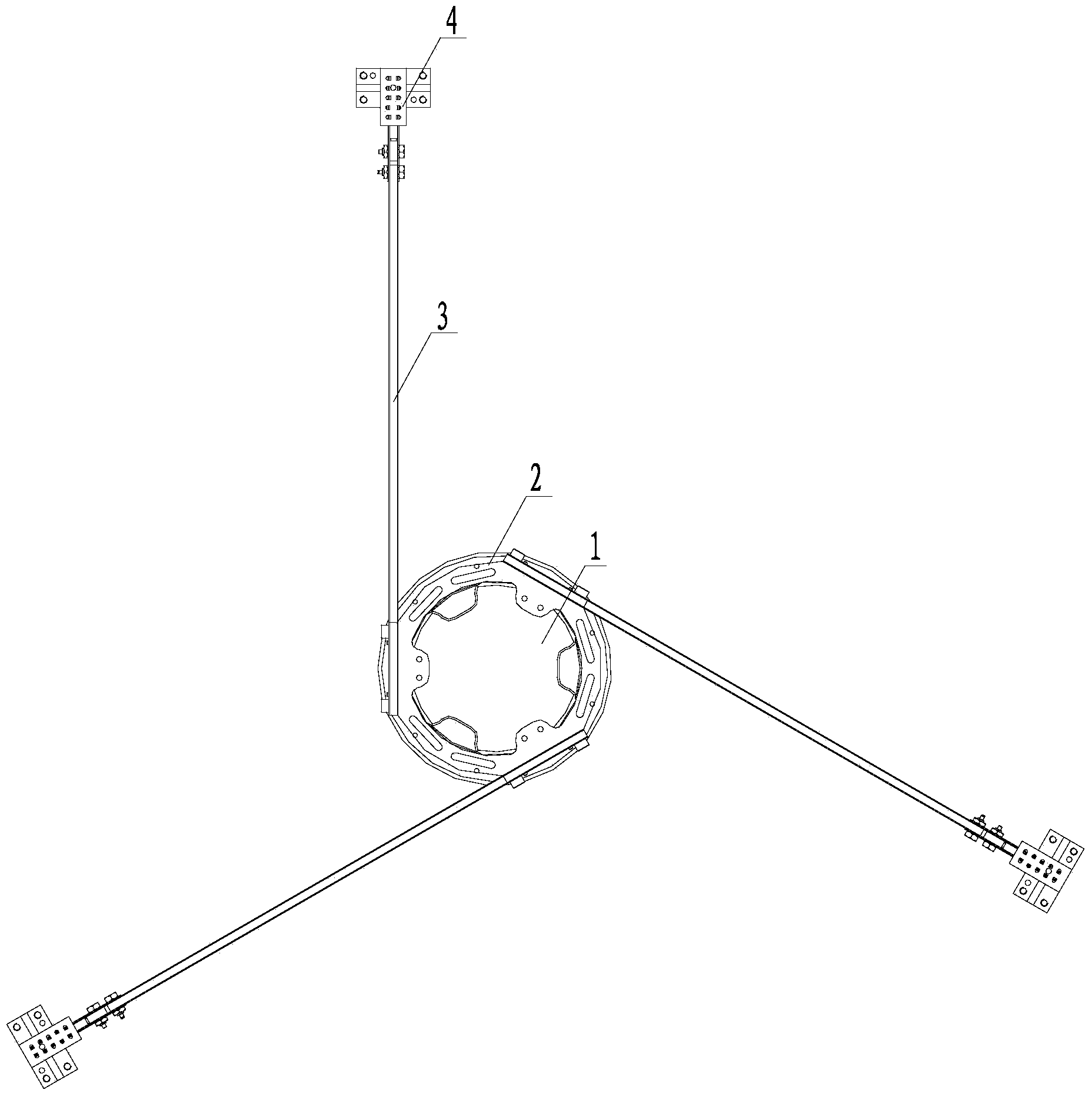
[0021] Such as Figure 1-Figure 7c As shown, the highly stable semi-flexible support structure for the secondary mirror of a space camera according to the present invention includes a secondary mirror support frame 2 , three support rods 3 , and three support seats 4 . Wherein, the secondary mirror support frame 2 is an annular frame, and the secondary mirror 1 is glued and fixed on the secondary mirror support frame 2 . Three support rods 3 are evenly distributed on the secondary mirror support frame 2, the first end of each support rod 3 is fixed on the secondary mirror support frame 2 along the tangential direction of the secondary mirror 1, and the three support rods 3 are positioned on the secondary mirror 1 The back of the reflecti...


PUM


Abstract

A high-stable and semi-flexible supporting structure for a secondary lens of a space camera comprises a secondary lens bearing frame, three supporting rods and three supporting bases. The secondary lens is fixed to the secondary lens bearing frame in an adhesive connection mode. The three supporting rods are uniformly distributed on the secondary lens bearing frame and located on the back side of the reflecting surface of the secondary lens, the first end of each supporting rod is fixed to the secondary lens bearing frame in the tangential direction of the secondary lens, and the second end of each supporting rod is connected to one corresponding supporting base. The supporting bases are connected to a front lens tube through screws. According to the high-stable and semi-flexible supporting structure, bolt rigid connection is adopted for the front segments of the connecting parts of the supporting bases and the supporting rods, structural adhesive and damping adhesive flexible connection is adopted for the rear segments of the connecting parts of the supporting bases and the supporting rods, and semi-flexible spring structures are arranged between the supporting bases and the supporting rods. Compared with a full-rigid connection structure or a full-flexible connection structure, the high-stable and semi-flexible supporting structure has high dynamic rigidity, static rigidity, damping properties and stability and meets the space environment use requirement of a secondary lens assembly of the large-aperture coaxial three-lens camera.

Description

technical field [0001] The invention belongs to the technical field of aerospace optical remote-sensing cameras, and in particular relates to a supporting structure for supporting secondary mirrors of large-caliber optical coaxial three-mirror cameras in aerospace. Background technique [0002] The secondary mirror assembly of the aerospace large-aperture optical coaxial three-mirror camera is suspended on the front lens barrel by a rod support, and because it is farthest from the installation base of the camera and the satellite, the secondary mirror and its supporting structure are subjected to the worst mechanical environment , in order to ensure that the secondary mirror can experience the emission vibration environment and is stable and reliable, the connection structure between the secondary mirror assembly and the installation interface must have good dynamic performance and high stability at the same time. [0003] The traditional rigid connection structure has high ...

Claims


Application Information

Patent Timeline
IPC IPC(8): G03B17/12G02B7/00G02B7/02
CPCG02B7/00G02B7/022G03B17/12
Inventor 罗世魁陈芳曹东晶潘宁贤史娇红吴杰宗肖颖张建国
Owner BEIJING RES INST OF SPATIAL MECHANICAL & ELECTRICAL TECH
Learn More