Ultra-fast continuous electron dynamic state observation device and method based on frequency domain space-time transformation

A spatiotemporal transformation, frequency domain technology, applied in optics, instruments, high-speed photography, etc., can solve the problems of low temporal resolution, unable to continuously image, difficult to meet the needs of scientific research and production, and achieve the effect of easy implementation and continuous shooting

Active Publication Date: 2015-02-25
BEIJING INSTITUTE OF TECHNOLOGYGY
View PDF6 Cites 20 Cited by
  • Summary
  • Abstract
  • Description
  • Claims
  • Application Information

AI Technical Summary

Problems solved by technology

[0006] The purpose of the present invention is to solve the problems that the existing imaging means have low time resolution, cannot perform continuous imaging on the process with an interval of femtosecond to picosecond level, and are difficult to meet the needs of scientific research and production. Ultrafast laser continuous imaging device and method of

Method used


Image

  • Ultra-fast continuous electron dynamic state observation device and method based on frequency domain space-time transformation
  • Ultra-fast continuous electron dynamic state observation device and method based on frequency domain space-time transformation
  • Ultra-fast continuous electron dynamic state observation device and method based on frequency domain space-time transformation

Examples


Embodiment Construction

[0028] In order to make the purpose, technical solution and advantages of the present invention more clear and definite, the technical solution of the present invention will be further described below in conjunction with the accompanying drawings and embodiments.

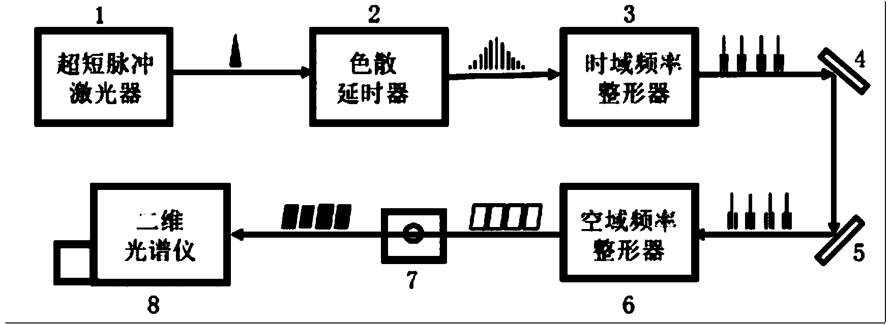
[0029] An ultrafast laser continuous imaging device based on frequency-domain space-time transformation, including an ultrafast laser 1, a dispersion delay device 2, a time-domain frequency shaper 3, a first broadband mirror 4, a second broadband mirror 5, A spatial frequency shaper 6 , an observation object 7 , and a two-dimensional spectrum analyzer 8 .

[0030] The connection relationship is as follows: firstly, the ultrafast laser 1 generates ultrafast laser pulses with a wide spectral width; then, after the beam passes through the dispersion delay device 2, the pulse width becomes wider and the components of different frequencies produce different delays; thereafter, The light beam passes through the time-domai...


PUM


Abstract

The invention relates to an ultra-fast laser continuous imaging device and method based on frequency domain space-time transformation, and belongs to the field of ultra-fast imaging. The device comprises an ultra-short pulse laser, a chromatic dispersion delayer, a time domain frequency shaping device, a first wide wave band reflector, a second wide wave band reflector, a space domain frequency shaping device and a two-dimensional CCD spectrograph. According to the method, the ultra-short pulse laser is used for producing the laser light within the spectral range, the chromatic dispersion delayer is used for changing the delay interval, the time domain frequency shaping device and the space domain frequency shaping device are used for shaping the frequency components of the laser light, the two-dimensional CCD spectrograph is used for carrying out detecting after the laser light passes a sample, and then the electron dynamic state of the sample can be obtained. By means of the device and method, the time resolving power can be improved to the femtosecond level, continuous shooting is achieved, complete shooting is carried out on the process without the repeated experiment condition, the shooting period and the shooting number can be controlled and adjusted, and the spectrograph is used for replacing an imaging system, and implementation is easy.

Description

technical field [0001] The invention relates to the detection of ultra-high time resolution ability of ultra-fast process, and belongs to the field of ultra-fast imaging. Background technique [0002] In the process of scientific research and technology development, it is often necessary to take continuous photos of a certain process with very short time intervals. For example, the materials in the laser manufacturing process directly affect and determine the quality and precision of subsequent manufacturing results, such as photon energy transfer and electronic excitation, and the observation of this process is very important. However, the duration of this process is short and the change is fast, on the order of femtoseconds (10 -15 s). The two-dimensional imaging observation of this time scale is of great significance to science and production. [0003] Traditional continuous imaging equipment cannot achieve femtosecond imaging. Relying on traditional mechanical method...

Claims


Application Information

Patent Timeline
Patent Type & Authority Applications(China)
IPC IPC(8): G03B39/00
Inventor 姜澜王安东曹强李晓炜余彦武谭旭东
Owner BEIJING INSTITUTE OF TECHNOLOGYGY
Why Eureka
Try Eureka