Aircraft skin milling efficient machining path automatic generating method

A technology for processing trajectory and aircraft skin, applied in computer control, instruments, simulators, etc., can solve problems such as insufficient flexibility, low processing and programming efficiency, programming stability, poor quality, etc., to achieve high accuracy and reduce programming. Workload, the effect of strong applicability

Active Publication Date: 2015-02-25
NANJING UNIV OF AERONAUTICS & ASTRONAUTICS
View PDF7 Cites 22 Cited by
  • Summary
  • Abstract
  • Description
  • Claims
  • Application Information

AI Technical Summary

Problems solved by technology

[0005] In view of the fact that the current commercial CAM software cannot provide satisfactory processing paths for the aircraft skin mirror milling mode, and the current manual programming and drawing of processing paths, low processing programming efficiency, poor programming stability, poor quality, and insufficient flexibility

Method used


Image

  • Aircraft skin milling efficient machining path automatic generating method
  • Aircraft skin milling efficient machining path automatic generating method
  • Aircraft skin milling efficient machining path automatic generating method

Examples


Embodiment Construction

[0053] The following is a detailed description of the technical solution of the present invention in conjunction with the accompanying drawings.

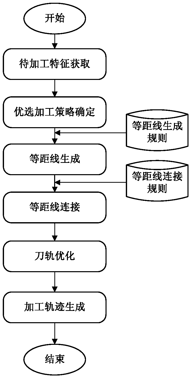
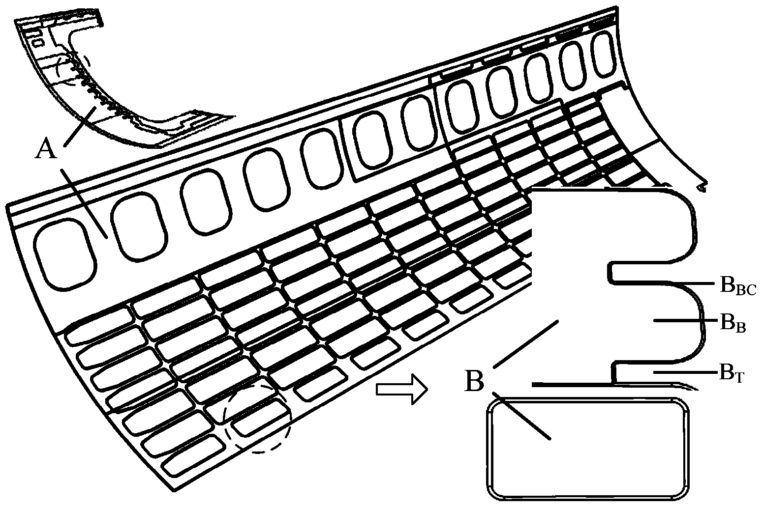
[0054] A method for automatically generating high-efficiency machining trajectories for aircraft skin milling, such as Figure 1-8 shown. The skin sag mainly includes the sag bottom B B , sunken bottom corner surface B BC and sunken top surface B T , the tool path is generally selected to be generated on the bottom surface, and the tool is moved along the bottom surface during processing. The tool axis is selected as the normal direction of the current tool contact, and the line along it is the tool path. The generation method is as follows:

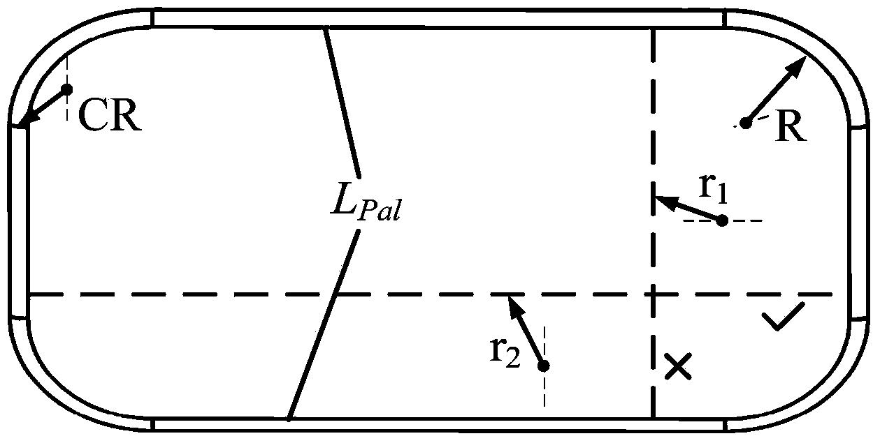
[0055] 1. Obtain the geometric elements of the cavity characteristics of the sag to be processed, and analyze the convex and concave characteristics of the contour, and based on the curvature characteristics of the sag bottom, combine the processing resource library to determine the tool pa...


PUM


Abstract

The invention discloses an aircraft skin milling efficient machining path automatic generating method and belongs to the technical field of CAD/CAM. The method is characterized by comprising the steps that skin part subsidence machining features are obtained at first; an preferable machining strategy is determined according to geometrical features of the subsidence machining features; an equidistant line is generated based on the subsidence preferable machining strategy and the typical machining technology; a machining path is generated based on the equidistant line connection rule; an equal-step-pitch, cross-free, cutter-lifting-free and residue-free efficient subsidence feature machining path is generated finally through residue detection processing. The efficient tool path generating method is provided for skin part numerical control milling, and the aircraft skin milling efficient machining path automatic generating method is particularly applied for tool path generation in the skin mirror image milling machining method, and is high in calculation efficiency, accuracy and applicability, and capable of relieving programming workloads of engineers greatly.

Description

technical field [0001] The present invention relates to a CAD / CAM technology for mechanical processing, in particular to a method for quickly generating machining tracks with equal steps and no crossing during aircraft skin sagging mirror milling, in particular to a method for automatically generating high-efficiency machining tracks for aircraft skin milling. generate method. Background technique [0002] With the rapid development of my country's aviation industry, more and more attention has been paid to large aircraft projects such as C919, and it has also promoted the technological improvement of the aviation manufacturing industry, especially in the field of CNC machining. Aircraft skin parts are important structural components in large aircraft. Compared with the previous aircraft skins connected by rivets, the current structurally integrated skins are large in size and complex in structure, with thin-walled, single-curvature or double-curvature profiles. The interio...

Claims


Application Information

Patent Timeline
Patent Type & Authority Applications(China)
IPC IPC(8): G05B19/4097
CPCG05B19/4099G05B2219/45174
Inventor 李迎光郝小忠周鑫马斯博刘长青
Owner NANJING UNIV OF AERONAUTICS & ASTRONAUTICS
Why Eureka
Try Eureka