
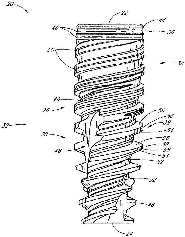
Tooth implant

A technology of implants and teeth, applied in dentistry, implants, dental prostheses, etc., can solve problems such as failure, low teeth implant fixtures, etc.

Inactive Publication Date: 2015-02-25
黄正斌
View PDF9 Cites 3 Cited by
  • Summary
  • Abstract
  • Description
  • Claims
  • Application Information

AI Technical Summary

Problems solved by technology

This force may cause failure of dental implant fixtures placed with low stability

Method used


Image

  • Tooth implant
  • Tooth implant
  • Tooth implant

Examples


Embodiment Construction

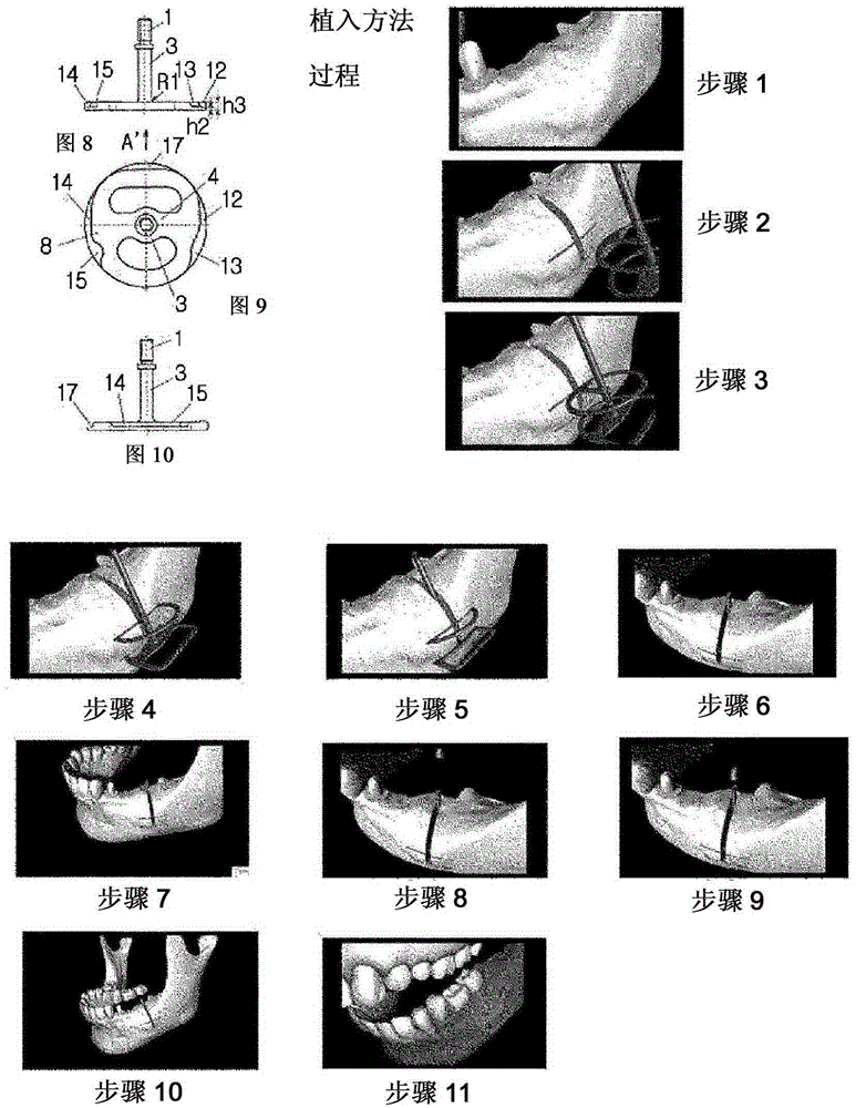
[0079] The present invention provides implant jigs for use in dental procedures. In the following, reference will be made to Figure 3 to Figure 19 The configuration and action of the present invention are described.

[0080] The background of Korean Patent Application No. 10-2012-0041160 (filed on April 19, 2012) entitled "Dental implant" filed by the present applicant has been explained in the background art, and the new Purpose of the implant jig development. The present invention adds three main implementations to the applicant's existing application. Figure 4a A total of four embodiments of the invention are shown. Figure 4b Five embodiments are shown including one that needs to be distinguished. exist Figure 4a In, (a) shows the two-body type implant jig of the prior application, and (b) shows the one-piece type implant jig. That is, (b) of FIG. 4 shows an embodiment in which the body section of the two-body type implant jig shown in (a) is applied to the one-pi...


PUM


Abstract

The present invention relates to a tooth implant for implanting a false tooth in the alveolar bone in dentistry instruments, and more particularly to an implant having functions of vertical self-drilling, horizontal self-drilling, self-cutting, self-condensing, and self-changing of direction, which increases the initial fixing force and ingression ability, has excellent correction capability to correct procedural errors, and minimizes the drilling operation heightening the probability of error or failure.

Description

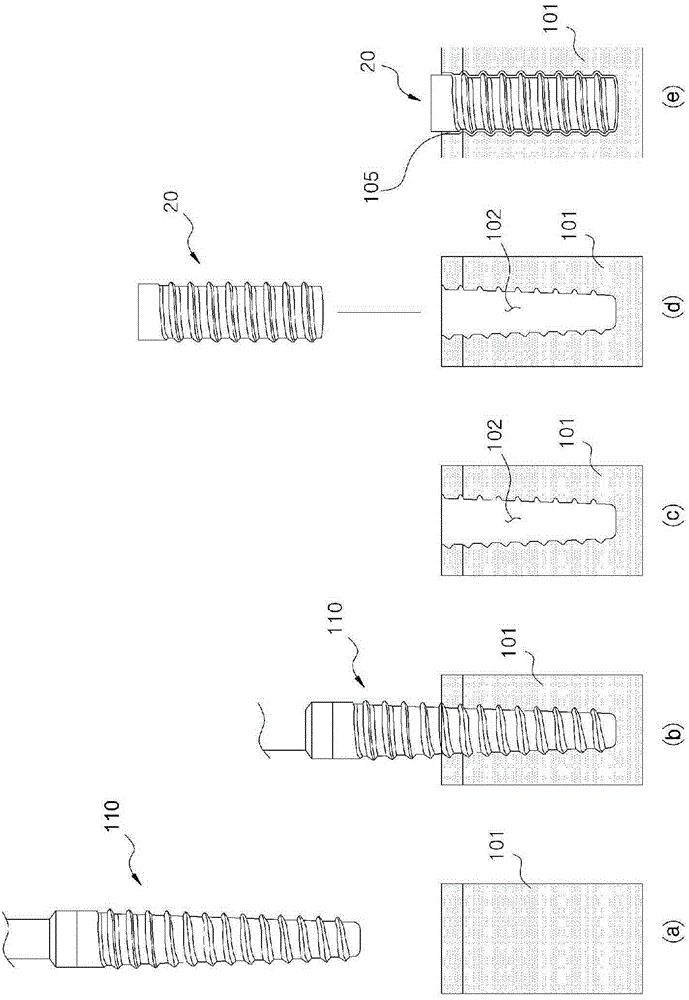
technical field [0001] The present invention relates to dental implant jigs, and more particularly, to such dental implant jigs having a vertical self-drilling function capable of vertical penetration, achieving high preliminary stability , and other associated elements that allow immediate loading. Background technique [0002] An implant generally refers to an artificial tooth obtained by inserting a screw made of titanium into an alveolar bone and engaging individual false teeth (or corrective teeth) with the inserted implant. [0003] Recent developments in implant technology and problems with conventional implants are discussed below. [0004] First, gaps inevitably form where false teeth (or orthodontics) join, which provides an environment for bacteria to multiply which, along with leftover food in the gaps, may cause bad breath. [0005] Second, according to figure 2 In the known implantation method shown in FIG. 2 , a surgical tool (or drill) 110 is used to cut a...

Claims


Application Information

Patent Timeline
Patent Type & Authority Applications(China)
IPC IPC(8): A61C8/00A61C13/263
CPCA61C8/0069A61C8/006A61C8/0018A61C8/0068A61C3/02A61C8/0048A61C8/0024A61C8/0045A61C8/0075A61C8/005
Inventor 黄正斌
Owner 黄正斌
Learn More