Contactless electrical-power-supplying transformer for moving body

A non-contact power supply and moving body technology, applied in the field of transformers, can solve the problems of power supply efficiency reduction and achieve the effect of suppressing leakage magnetic field

Inactive Publication Date: 2015-02-25
TECHNOVA
View PDF9 Cites 6 Cited by
  • Summary
  • Abstract
  • Description
  • Claims
  • Application Information

AI Technical Summary

Problems solved by technology

If the leakage magnetic fluxes 68 and 69 penetrate into the iron plate of the floor of the vehicle body, etc., an induced current will flow and the iron plate will be heated, and the power supply efficiency will decrease.

Method used


Image

  • Contactless electrical-power-supplying transformer for moving body
  • Contactless electrical-power-supplying transformer for moving body
  • Contactless electrical-power-supplying transformer for moving body

Examples


Embodiment Construction

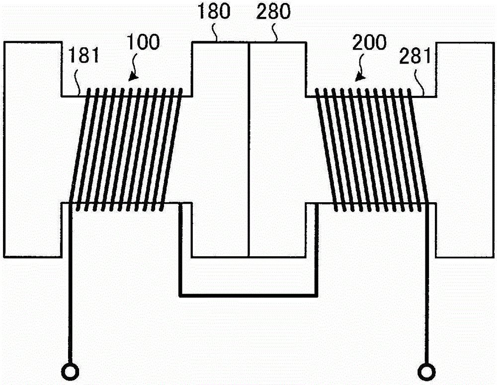
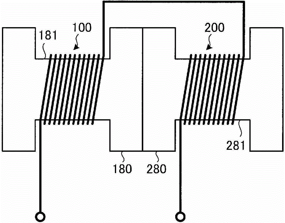
[0072] Figure 1A , Figure 1B A power transmission coil of a mobile body non-contact power supply transformer according to an embodiment of the present invention is schematically shown. The power receiving coil also has the same structure.

[0073] This power transmission coil is composed of a combined double-wound coil in which two single double-wound coils 100 and 200 are combined.

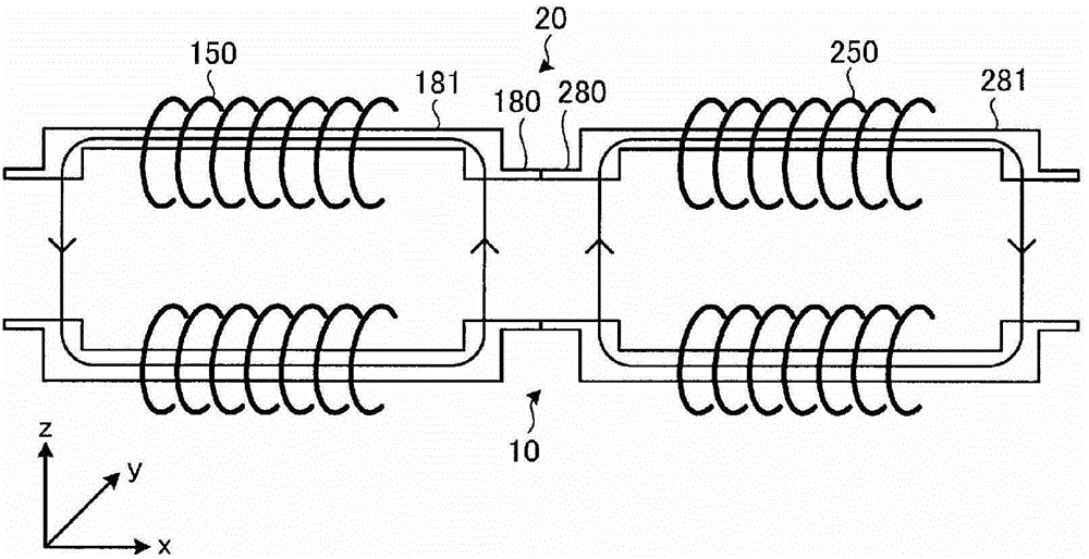
[0074] The single double-side wound coils 100 and 200 are formed by winding Litz wire around the wound portion of the H-shaped core, specifically, as Figure 7A , Figure 7B As shown, the H-shaped core is formed by a pair of parallel magnetic pole cores 80 and a winding core 81 orthogonal to the magnetic pole cores 80 . Both the pole core 80 and the winding core 81 are ferrite cores.

[0075] The winding part 50 around which the electric wire is wound is attached to the center of the winding core 81 , and both ends of the ferrite plate protruding from both sides of the winding part 50 are ...


PUM


Abstract

A transmitting coil (10) and / or a receiving coil (20) are / is configured from a double-sided winding coil combination formed by combining a plurality of unitary double-sided winding coils (100, 200). From the unitary double-sided winding coils (100, 200) is selected a unitary double-sided winding coil in which the leakage flux around a moving body does not exceed a predetermined value when two unitary double-sided winding coils are placed in placement positions on the moving body, and the number of unitary double-sided winding coils to be combined in the double-sided winding coil combination is set so that the product obtained by multiplying the electrical power feed capacity of the unitary double-sided winding coils by the quantity thereof satisfies the electrical power feed capacity of the contactless electrical power feed transformer. It is possible both to reduce the leakage flux and readily increase capacity according to the number of combinations.

Description

technical field [0001] The present invention relates to a non-contact power supply transformer for a mobile body that supplies power to a mobile body such as an electric vehicle in a non-contact manner. Interchangeable transformers for types of contactless power supply transformers. Background technique [0002] As a system for charging the batteries of electric vehicles and plug-in hybrid vehicles, a system such as Figure 18 As shown, the secondary side coil (power receiving coil) 20 of the non-contact power supply transformer is mounted on the floor surface of the vehicle, and power is supplied in a non-contact manner from the primary side coil (power transmission coil) 10 installed on the ground side by electromagnetic induction. Way. [0003] In the following patent document 1, a kind such as Figure 19A , Figure 19B Coils formed by spirally and flatly winding electric wires on one side of the flat ferrite cores 21 and 31 as shown are used as the transmission coil a...

Claims


Application Information

Patent Timeline
Patent Type & Authority Applications(China)
IPC IPC(8): H01F38/14B60L5/00H02J17/00
CPCB60L1/02B60L11/1833Y02T90/12B60L2240/36Y02T90/125H01F38/14B60L11/182Y02T90/14Y02T90/121Y02T90/122H01F27/255Y02T10/7005H01F27/306Y02T10/7072B60L2270/147B60L53/36B60L53/122Y02T10/70H02J50/70H02J50/10
Inventor 阿部茂金子裕良保田富夫岸洋之
Owner TECHNOVA
Why Eureka
Try Eureka