
Automatic cleaning system of filter stick transmitting pipeline and detection control method of automatic cleaning system

A filter rod launch and pipeline technology, which is applied to cleaning methods and utensils, chemical instruments and methods, cleaning hollow objects, etc. Convenience, simple operation of the device, and improved sensitivity

Active Publication Date: 2015-03-04
CHANGDE RUIHUA MFG
View PDF6 Cites 5 Cited by
  • Summary
  • Abstract
  • Description
  • Claims
  • Application Information

AI Technical Summary

Problems solved by technology

[0003] 1. Cannot effectively and quickly determine whether the pipeline is blocked;
[0004] 2. After the pipeline is dredged, personnel need to rely on experience to judge whether it is dredged, which will cause misoperation or redundant operation, which will affect the efficiency and use effect;
[0005] 3. Because the sensitivity of the judgment is not high, after the blockage is detected, the filter rod has been blocked too much in the pipeline, which will bring trouble to the subsequent cleaning work;
[0006] 4. The design of the device is unreasonable, the action is not flexible, and the moving parts cannot move independently, and the operation of multiple functions cannot be completed

Method used


Image

  • Automatic cleaning system of filter stick transmitting pipeline and detection control method of automatic cleaning system
  • Automatic cleaning system of filter stick transmitting pipeline and detection control method of automatic cleaning system
  • Automatic cleaning system of filter stick transmitting pipeline and detection control method of automatic cleaning system

Examples


Embodiment Construction

[0020] Below in conjunction with accompanying drawing, the present invention is described in detail as follows:

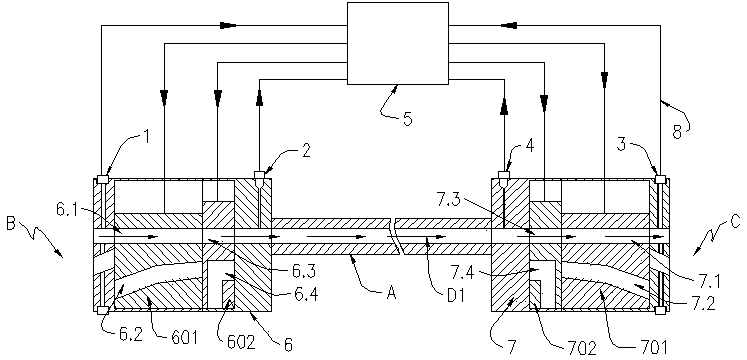
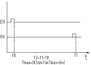
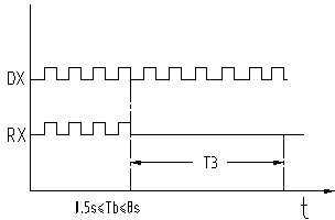
[0021] exist figure 1 Among them, the automatic blockage removal system for the filter rod launch pipeline includes a launch end cleaning device 6, the launch end cleaning device 6 is installed between the filter stick launcher B and the filter stick launch pipe A, and the receiving end cleaning device 7 is installed on the filter stick Between the transmitting pipe A and the filter rod receiver C; the optical fiber detector 1 at the transmitting end and the air pressure detector 2 at the transmitting end are installed on the cleaning device 6 at the transmitting end, the optical fiber detector 3 at the receiving end and the air pressure detector 4 at the receiving end are installed on the receiving end on the end cleaning device 7; the programmable logic controller 5 is respectively connected with the transmitting end optical fiber detector 1, the transmitting ...


PUM


Abstract

The invention relates to an automatic cleaning system of a filter stick transmitting pipeline and a detection control method of the automatic cleaning system. A transmitting end cleaning device is installed between a filter stick transmitter and the filter stick transmitting pipeline, and a receiving end cleaning device is installed between the filter stick transmitting pipeline and a filter stick receiver; a transmitting end optical fiber detector and a transmitting end air pressure detector are installed on the transmitting end cleaning device, and a receiving end optical fiber detector and a receiving end air pressure detector are installed on the receiving end cleaning device; a programmable logic controller is respectively connected with the devices through control lines. The detection method can be used for determining that the filter stick transmitting pipeline is blocked and determining that the pipeline is unblocked after the pipeline is cleaned by high-pressure gas blown into the pipeline respectively from a filter stick transmitting end or a filter stick receiving end. The automatic cleaning system and the detection control method have the advantages that the conditions of both ends of the filter stick transmitting pipeline can be effectively monitored; whether the pipeline is blocked is effectively determined in time; whether the pipeline is unblocked is effectively and rapidly determined.

Description

technical field [0001] The invention relates to a cleaning technology for a filter rod launching pipeline in the cigarette industry, in particular to an efficient and easy-to-operate filter rod launching pipeline automatic cleaning system and a detection and control method thereof. Background technique [0002] At present, when the filter rod conveying pipeline of a cigarette factory is blocked, workers need to manually blow through the blocked pipeline from the opposite direction to solve the problem. In the case of serious blockage, it is necessary for personnel to go to the roof of the factory building to dismantle the pipes. However, due to the high filter rod conveying pipes, workers have certain dangers when operating, and the labor intensity is high and the work efficiency is low. Therefore, many cigarette factories It is very urgent for an automatic and intelligent filter rod launch pipeline cleaning system. In view of this situation, the applicant of the present in...

Claims


Application Information

Patent Timeline
IPC IPC(8): B08B9/032G01V8/10
CPCB08B9/032B08B2209/032G01V8/10
Inventor 谢亮华钱本炎练孔辉夏先林
Owner CHANGDE RUIHUA MFG
Learn More