A worm machining mechanism with a driving motor partition

A technology for driving motors and processing mechanisms, which is applied to components with teeth, worms, mechanical equipment, etc., can solve problems such as difficulty in reducing costs, improving processing speed and accuracy, low worm transmission efficiency, and difficulty in ensuring the accuracy of the cogging shape and position. And other issues

Inactive Publication Date: 2016-08-24
STATE GRID CORP OF CHINA +1
View PDF6 Cites 0 Cited by
  • Summary
  • Abstract
  • Description
  • Claims
  • Application Information

AI Technical Summary

Problems solved by technology

4. The efficiency of worm transmission is low. It is generally believed that the efficiency of worm transmission is lower than that of gear transmission.
However, the shape processing and manufacturing of the worm gear tooth profile is troublesome, and it is difficult to ensure the accuracy of the processed tooth groove shape and position
[0003] In particular, in some specific application areas, such as soft materials (such as plastics) processing, traditional metal processing methods will be difficult to meet the requirements of reducing costs and improving processing speed and accuracy

Method used


Image

  • A worm machining mechanism with a driving motor partition
  • A worm machining mechanism with a driving motor partition

Examples


Embodiment Construction

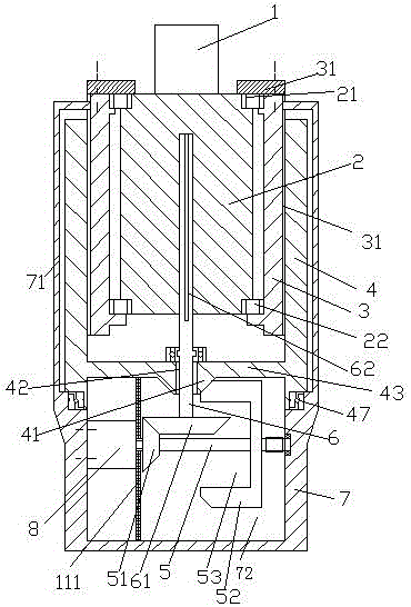
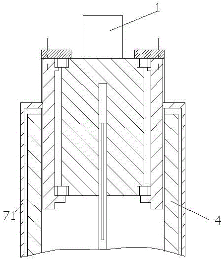
[0014] Attached below Figure 1-2 , the present invention will be described in detail.

[0015] A worm processing mechanism with a drive motor baffle plate 111, used to process a blank 1 into a worm, the processing mechanism includes a blank carrier 2, a sleeve 3 with external threads, and a drive sleeve with internal threads The cylinder 4 and the frame 7, the blank carrier 2 is used to carry the blank 1, the upper end and the lower end of the blank carrier 2 are respectively relative to the sleeve 3 with external thread through the upper bearing 21 and the lower bearing 22 Axially fixedly installed in the sleeve 3 with external thread, the sleeve 3 with external thread is screwed into the drive sleeve 4 with internal thread, and the drive sleeve with internal thread The lower end of 4 is rotatably mounted on the frame 7 through the thrust bearing 47, and the inside of the frame 7 has a chamber 72, and in the chamber 72, a drive is fixed on the left inner wall of the chamber...


PUM


Abstract

The invention relates to a worm rod processing mechanism with a driving motor separation baffle plate (111). The worm rod processing mechanism is used for processing a blank (1) into a worm rod, and comprises a blank carrying element (2), a sleeve (3) with external screw threads, a driving sleeve (4) with internal screw threads and a machine frame (7), wherein the blank carrying element (2) is used for carrying the blank (1), the upper end and the lower end of the blank carrying element (2) are respectively and fixedly arranged in the sleeve (3) with the external screw threads through an upper bearing (21) and a lower bearing (22) in a direction opposite to the axial direction of the sleeve (3) with the external screw threads, the sleeve (3) with the external screw threads is matched in the driving sleeve (4) with the internal screw threads through screw threads, and the lower end of the driving sleeve (4) with the internal screw threads is rotatablely arranged on the machine frame (7) through a thrust bearing (47).

Description

technical field [0001] The present application relates to the field of worm machining, in particular to a worm machining mechanism with a drive motor baffle. Background technique [0002] The worm drive is composed of a worm and a worm gear, and the worm is generally the active part. Worms, like threads, can be divided into right-handed and left-handed. Worm drive has the following advantages: 1. Large transmission ratio and compact structure. The number of worm heads is represented by Z1 (generally Z1=1~4), and the number of worm gear teeth is represented by Z2. It can be seen from the transmission ratio formula I=Z2 / Z1 that when Z1=1, that is, the worm is single-headed, and the worm must turn Z2 to turn the worm wheel for one turn, so a large transmission ratio can be obtained. Generally, in power transmission, take The transmission ratio I=10-80; in the indexing mechanism, I can reach 1000. Such a large transmission, such as gear transmission, needs to adopt multi-sta...

Claims


Application Information

Patent Timeline
Patent Type & Authority Patents(China)
IPC IPC(8): B23F13/00
Inventor 马鲁霞王鑫萌崔贵玲张岩王守杰刘再飞万粉花阴春明尹海华田文娜董正芝谢孟丽魏敏汤辉李海奇李英超舒秀珍孙运宾田颖李丽
Owner STATE GRID CORP OF CHINA
Why Eureka
Try Eureka