Outer circle turning clamp of thin wall bearing ring

A thin-walled bearing and outer circle turning technology, which is applied in the field of bearing processing fixtures, can solve the problems of large processing size error, reduced production efficiency, and low pass rate, so as to reduce processing size error, improve turning pass rate, and reduce production. cost effect

Inactive Publication Date: 2015-03-04
JIANGYIN JIB WD PRECISION
View PDF4 Cites 4 Cited by
  • Summary
  • Abstract
  • Description
  • Claims
  • Application Information

AI Technical Summary

Problems solved by technology

Due to the thin wall of the bearing ring, the clamping force is slightly larger, and the bearing ring is easily deformed by force, resulting in the misalignment of the clamping point and the positioning point of the ring, and it is difficult to effectively control the clamping force
After the turning process is completed, in the clamping state, the size of the measured outer circle is qualified. When the clamping force is removed, the ferrule is elastically deformed due to the internal stress generated by the clamping force on the ferrule during processing, resulting in The size of the thin-walled ferrule is inconsistent before and after the clamping force is removed, and the processing size error is large, resulting in more defective products or even waste products, and the pass rate is low, resulting in increased production costs and reduced production efficiency.

Method used


Image

  • Outer circle turning clamp of thin wall bearing ring

Examples


Embodiment Construction

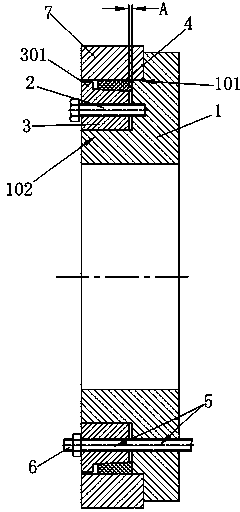
[0012] The specific implementation manners of the present invention will be further described in detail below in conjunction with the accompanying drawings.

[0013] Such as figure 1 As shown, the present invention includes a clamp body 1, the clamp body 1 is disc-shaped, the front end of the clamp body 1 is provided with a positioning boss 101 for positioning the inner hole of one end of the thin-walled bearing ring, and the front part of the positioning boss 101 is provided with a sliding guide part 102, the clamp body 1, the positioning boss 101 and the sliding guide part 102 are coaxially arranged, the pressing ring 3 is slidably fitted on the sliding guide part 102, the pressing ring 3 is provided with an outer tapered surface, and the tensioning ring 4 is set on the pressing part Outside the tightening ring 3, the tensioning ring 4 is provided with an inner taper hole matching the outer cone surface of the compression ring 3; the tensioning ring 4 is made of hard rubber,...


PUM


Abstract

The invention relates to an outer circle turning clamp of a thin wall bearing ring. The outer circle turning clamp is characterized by comprising a disc-shaped clamp body, wherein the front end of the clamp body is provided with a positioning boss for positioning an inner hole of one end of the thin wall bearing ring, the front part of a positioning boss is provided with a slide guide part, a pressing ring glidingly sleeves the slide guide part, and is provided with an outer conical surface, an expansion ring sleeves the exterior of the pressing ring, and is provided with an inner conical hole which is matched with the outer conical surface of the pressing ring, at least two limiting screws penetrate through holes of the pressing ring and are connected with the clamp body, a plurality of bolt holes are respectively and uniformly formed in the clamp body and the pressing ring and are connected with a main shaft of a lathe, and a pressing gap is formed between the inner end surface of the pressing ring and the front end surface of the clamp body. The outer circle turning clamp has the advantages that the structure is simple, the clamping is convenient and rapid, the direction of clamping force is coincided with the positioning point of the bearing ring, the positioning is accurate, the clamping force is stable, the error of processing size is reduced, the turning qualified rate of the thin wall bearing ring is improved, the processing efficiency is improved, and the production cost is reduced.

Description

technical field [0001] The invention relates to a bearing processing jig, in particular to a thin-walled bearing ring outer circle turning jig. Background technique [0002] The ring is an important part of the bearing. During the turning process of the inner hole or outer circle of the thin-walled bearing ring, there is a problem of positioning and clamping difficulties, which affects the turning efficiency and quality of the thin-walled bearing ring. [0003] The clamping method of the existing thin-walled bearing ring outer circle turning jig is as follows: use a cast iron tire slightly larger than the ring to be processed, and open a through groove on the mold for deformation after the mold is clamped. When clamping on the lathe, the deformation of the mold is used to achieve the purpose of clamping the thin-walled bearing ring. Due to the thin wall of the bearing ring, the clamping force is slightly larger, and the bearing ring is easily deformed by force, resulting in...

Claims


Application Information

Patent Timeline
IPC IPC(8): B23Q3/12
CPCB23Q3/12
Inventor 程万丁沈强
Owner JIANGYIN JIB WD PRECISION
Why Eureka
Try Eureka