Fixing device used for rubber cutting and using method of fixing device

A fixing device and rubber technology, applied in the field of rubber processing, can solve the problems of affecting the cutting quality, the cutting machine is not labor-saving, etc., and achieve the effect of ensuring the cutting quality

Inactive Publication Date: 2015-03-04
SICHUAN FUDI NEW ENERGY
View PDF7 Cites 1 Cited by
  • Summary
  • Abstract
  • Description
  • Claims
  • Application Information

AI Technical Summary

Problems solved by technology

[0006] Aiming at the problem that the aforementioned manual rubber cutting machine is not labor-saving enough and affects the cutting quality, the present invention provides a fixing device for rubber cutting and its use method, which saves labor and ensures the cutting quality of the cutting material

Method used


Image

  • Fixing device used for rubber cutting and using method of fixing device
  • Fixing device used for rubber cutting and using method of fixing device
  • Fixing device used for rubber cutting and using method of fixing device

Examples


Embodiment 1

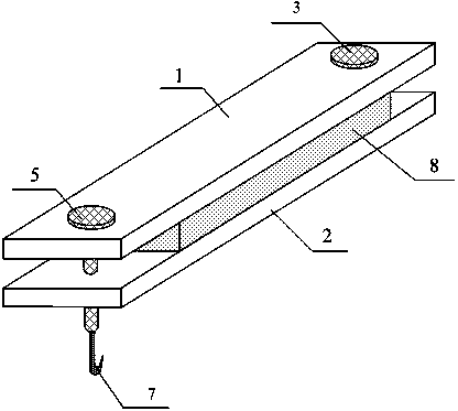
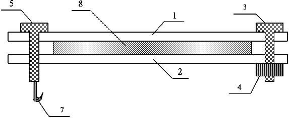
[0025] Embodiment one, figure 1 A schematic structural view of the first fixing device for rubber cutting of the present invention is shown, figure 2 A schematic cross-sectional view of the first fixing device for rubber cutting of the present invention is shown. The fixing device for rubber cutting is characterized in that it comprises: an upper splint 1, a lower splint 2, a first rivet 3, a nut 4, a second rivet 5 and a hook 7; There is a hole matched with the first rivet 3, the first rivet 3 passes through the holes of the upper splint 1 and the lower splint 2, the lower end of the first rivet 3 cooperates with the nut 4; the left end of the upper splint 1 and the lower splint 2 is provided with a The second rivet 5 fits through the holes of the upper splint 1 and the lower splint 2 , and the lower end of the second rivet 5 is connected with the hook 7 . After determining the cutting size of the cutting material 8, the processing personnel add a heavy object to the hook ...

Embodiment 2

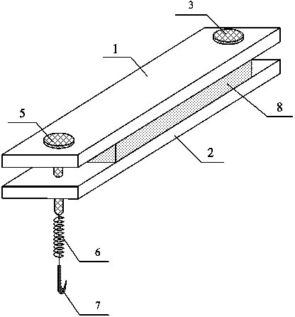
[0034] Embodiment two, image 3 A schematic cross-sectional view of the second fixing device for rubber cutting of the present invention is shown. The fixing device for rubber cutting in the second embodiment is different from the fixing device for rubber cutting in the first embodiment in that it includes: the lower end of the second rivet 5 is connected to one end of the spring 6, and the other end of the spring 6 is connected to the hook 7 connect.

[0035] The using method of the fixing device for rubber cutting provided in the second embodiment is different from the first embodiment in that:

[0036] Step 102 , pull down the spring to let the hook hang on the ground or a heavy object on the ground, so that the upper splint 1 and the lower splint 2 clamp the cutting material 8 .

[0037] Step 104, pull down the spring to unhook the hook, loosen the upper splint 1, and translate the cutting material 8 at the same time to determine the next cutting width, and then cycle th...


PUM


Abstract

The invention relates to the field of rubber processing, and discloses a fixing device for rubber cutting and a using method of the fixing device. The fixing device for the rubber cutting is characterized by comprising an upper clamp plate (1), a lower clamp plate (2), a first rivet (3), a nut (4), a second rivet (5) and a hanging hook (7), wherein holes which are matched with the first rivet (3) are formed in the right ends of the upper clamp plate (1) and the lower clamp plate (2); the first rivet (3) penetrates through the holes of the upper clamp plate (1) and the lower clamp plate (2); the lower end of the first rivet (3) is matched with the nut (4); holes which are matched with the second rivet (5) are formed in the left ends of the upper clamp plate (1) and the lower clamp plate (2); the second rivet (5) penetrates through the corresponding holes of the upper clamp plate (1) and the lower clamp plate (2); the lower end of the second rivet (5) is connected with the hanging hook. When rubber is cut, the upper clamp plate is pulled down through a heavy object on the hanging hook, so that the upper clamp plate, the lower clamp plate and a cut material are kept in a compressed state; therefore, an effect of saving labor when the rubber is cut is achieved. Meanwhile, when the cut material is cut, the cut material cannot loose, so that the cutting quality is ensured.

Description

technical field [0001] The invention relates to the field of rubber processing, in particular to a fixing device for rubber cutting and a use method. Background technique [0002] The rubber cutting machine is an important processing equipment in the modern rubber processing industry. Its function is mainly to divide the rubber material according to the predetermined size for subsequent processing. According to the control system of the glue cutting machine, it is divided into two types: manual glue cutting machine and automatic glue cutting machine. The structure of the automatic glue cutting machine is complex, mainly composed of glue cutting knife, frame, working cylinder, hydraulic system and other components. Its advantage is efficiency. High, but there are also disadvantages such as high price, troublesome maintenance and complicated process. Therefore, in the small batch or small-scale production of the processing plant, the manual glue cutting machine is still mainl...

Claims


Application Information

Patent Timeline
Patent Type & Authority Applications(China)
IPC IPC(8): B26D7/02B26D1/06
Inventor 王鸿徐竹
Owner SICHUAN FUDI NEW ENERGY
Why Eureka
Try Eureka