Feeding device for circular cans

A technology of feeding device and round cans, which is applied in the direction of conveyor objects, transportation and packaging, etc., can solve the problems of high equipment cost and low efficiency of manual transmission, and achieve the effect of low cost, simple structure and improved efficiency

Inactive Publication Date: 2015-03-04
重庆瑶红食品有限公司
View PDF0 Cites 13 Cited by
  • Summary
  • Abstract
  • Description
  • Claims
  • Application Information

AI Technical Summary

Problems solved by technology

[0003] The present invention mainly solves the problem of high equipment cost or low efficiency of manual transmission in the existing canned food transmission technology

Method used


Image

  • Feeding device for circular cans

Examples


Embodiment Construction

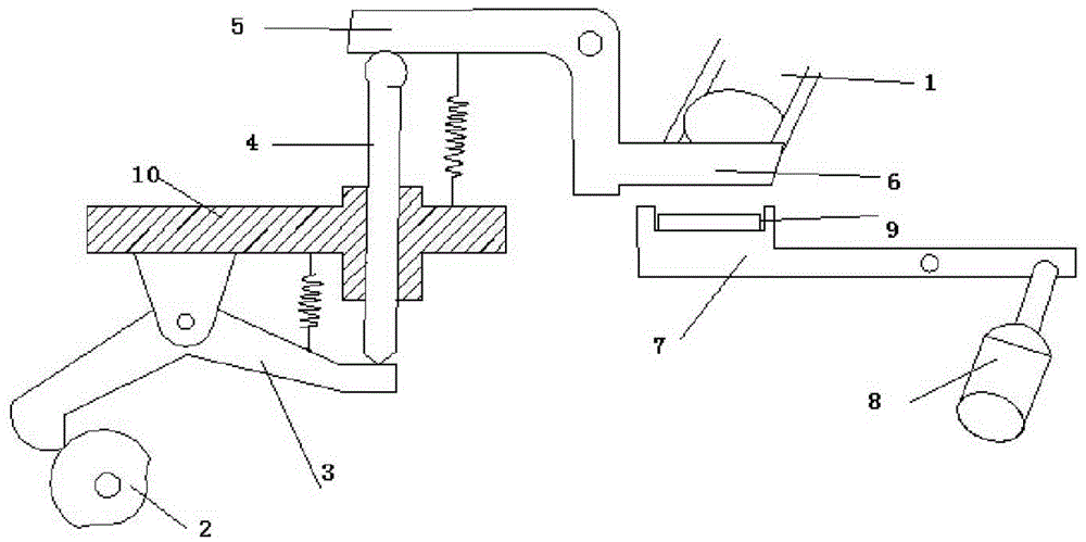
[0014] The reference signs in the description of the drawings are: storage tank 1, cam mechanism 2, lever type swing rod 3, push rod 4, "L" shaped rotating arm 5, baffle plate 6, rotary table 7, cylinder 8, assembly Clip groove 9, frame 10.

[0015] Such as figure 1 As shown, the technical solution provides a feeding device for round cans, including a frame 10, a storage tank 1, a control device and a steering device, and the storage tank 1 is an inclined chute. The control device includes a cam mechanism 2, a lever swing lever 3, a push rod 4, an "L" shaped rotating arm 5 and a baffle plate 6. Lever type swing bar 3 is " V " shape structure, and middle part is hinged on the frame 10 , the left end of lever type swing bar 3 is connected with the follower of cam mechanism 2 , and its right end is hinged with the lower end of push rod 4 . In addition, a tension spring is connected between the right end of the lever swing rod 3 and the frame 10 . A slide rail is vertically ins...


PUM


Abstract

The invention relates to a feeding device for circular cans. A material storage groove is an inclined sliding groove; a control device comprises a cam mechanism, a lever type swinging rod, a pushing rod, an L-shaped rotary arm and a baffle; the middle part of the lever type swinging rod is hinged to a machine frame; the two ends of the lever type swinging rod are connected with the cam mechanism and the pushing rod respectively; the pushing rod is vertically and slidably connected to the machine frame; the middle part of the L-shaped rotary arm is hinged to the machine frame; the two ends of the L-shaped rotary arm are connected with the pushing rod and the baffle respectively; the baffle corresponds to the output end of the material storage groove; a steering device comprises a rotary workbench and a cylinder; an assembly clamping groove is formed in the rotary workbench and is positioned below the material storage groove; the middle part of the rotary workbench is hinged to the machine frame; one end of the rotary workbench is connected with the cylinder. The feeding device is implemented to mainly solve the problem that the needed equipment cost is high or the efficiency of a manual conveying mode is low in an existing conveying technology for canned food.

Description

technical field [0001] The present invention relates to a conveying device, in particular to a feeding device for round cans. Background technique [0002] Because canned food has a long shelf life and is easy to carry, it is one of the favorite products when people live at home and travel. After packaging, the canned food still needs to be packaged, tested or otherwise processed. In the existing conveying technology for cans, the method of manipulator or manual separation is generally used, and some of them are clamped by manipulators, but the cans are easy to deform, and it is not easy to apply too much force to them, otherwise it will damage its appearance and affect Sales. Therefore, equipment with high precision is required to complete, but such equipment is generally expensive and not suitable for small processing plants. For the manual transmission method, a pile of cans is manually separated, and then the separated items are placed one by one at the station to be p...

Claims


Application Information

Patent Timeline
Patent Type & Authority Applications(China)
IPC IPC(8): B65G47/82
Inventor 曾秀琴
Owner 重庆瑶红食品有限公司
Why Eureka
Try Eureka