
Heating floor tile

A floor tile and heating technology, applied in the field of heating floor tiles, can solve problems such as unreasonable structural design, increase maintenance costs, and reduce production efficiency, so as to improve heat reflection and radiation capabilities, good heat insulation functions, and improve production efficiency effect

Inactive Publication Date: 2015-03-04
CHENGDU JINHUI TECH
View PDF6 Cites 0 Cited by
  • Summary
  • Abstract
  • Description
  • Claims
  • Application Information

AI Technical Summary

Problems solved by technology

[0004] The heating wire threading hole is set, and the heating wire is inserted into the heating wire threading hole. Compared with the ordinary aluminum alloy floor in the prior art, this patent document utilizes the characteristics of high thermal conductivity of metals such as aluminum alloys. Under the action of electric energy conversion, the heat energy converted from electric energy stays on the ground or the bottom floor of the room for a long time to achieve the purpose of room heating; however, due to the unreasonable structural design, there are many shortcomings, mainly in: the electric heating wire is threaded through the electric heating wire The hole operation is quite difficult, which greatly reduces the production efficiency. During long-term use, once the heating wire is burned, it is extremely inconvenient to replace, which increases the maintenance cost.

Method used


Image

  • Heating floor tile
  • Heating floor tile
  • Heating floor tile

Examples


Embodiment 1

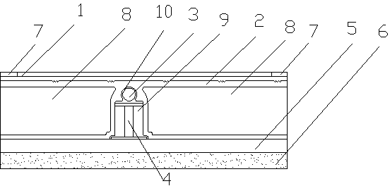
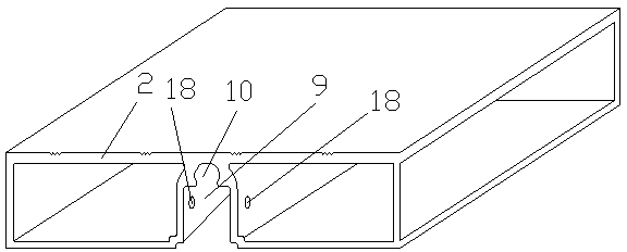
[0036] A heated floor tile, comprising a solid wood board 1 and an aluminum frame 2, the solid wood board 1 is located above the aluminum frame 2, the lower surface of the solid wood board 1 is fixedly connected to the upper surface of the aluminum frame 2, and also includes a heating cable 3 and a support 4. Reflective film 5 and foam concrete 6, the four corners of the upper surface of the solid wood board 1 are bonded with ceramic plates 7, the aluminum frame 2 is integrally formed, and the lower surface of the aluminum frame 2 protrudes from the upper surface to form a There are cavities 8 on both sides of the accommodating groove. The accommodating groove is composed of a supporting groove 9 and a groove 10 above the supporting groove 9. The heating cable 3 is embedded in the groove 10. The The support member 4 is clamped in the support card slot 9, the cross section of the support member 4 is in the shape of "I", the reflective film 5 is fixedly connected with the lower s...

Embodiment 2

[0039] A heated floor tile, comprising a solid wood board 1 and an aluminum frame 2, the solid wood board 1 is located above the aluminum frame 2, the lower surface of the solid wood board 1 is fixedly connected to the upper surface of the aluminum frame 2, and also includes a heating cable 3 and a support 4. Reflective film 5 and foam concrete 6, the four corners of the upper surface of the solid wood board 1 are bonded with ceramic plates 7, the aluminum frame 2 is integrally formed, and the lower surface of the aluminum frame 2 protrudes from the upper surface to form a There are cavities 8 on both sides of the accommodating groove. The accommodating groove is composed of a supporting groove 9 and a groove 10 above the supporting groove 9. The heating cable 3 is embedded in the groove 10. The The support member 4 is clamped in the support card slot 9, the cross section of the support member 4 is in the shape of "I", the reflective film 5 is fixedly connected with the lower s...

Embodiment 3

[0043] A heated floor tile, comprising a solid wood board 1 and an aluminum frame 2, the solid wood board 1 is located above the aluminum frame 2, the lower surface of the solid wood board 1 is fixedly connected to the upper surface of the aluminum frame 2, and also includes a heating cable 3 and a support 4. Reflective film 5 and foam concrete 6, the four corners of the upper surface of the solid wood board 1 are bonded with ceramic plates 7, the aluminum frame 2 is integrally formed, and the lower surface of the aluminum frame 2 protrudes from the upper surface to form a There are cavities 8 on both sides of the accommodating groove. The accommodating groove is composed of a supporting groove 9 and a groove 10 above the supporting groove 9. The heating cable 3 is embedded in the groove 10. The The support member 4 is clamped in the support card slot 9, the cross section of the support member 4 is in the shape of "I", the reflective film 5 is fixedly connected with the lower s...


PUM


Abstract

The invention discloses a heating floor tile, which comprises a solid wood plate and an aluminum sectional frame, and also comprises a heating cable, a support element, a reflecting film and foam concrete, wherein ceramic plates are bonded on four corners of the upper surface of the solid wood plate; the aluminum sectional frame is of an integrally formed structure; the lower surface of the aluminum sectional frame is upwards projected to be combined with the upper surface to form an accommodating groove; cavities are formed in two sides of the accommodating groove; the accommodating groove consists of a support clamp groove and a groove positioned above the support clamp groove; the heating cable is embedded into the groove; the support element is clamped and connected into the support clamp groove; the cross section of the support element is in an I shape; the reflecting film is fixedly connected with the lower surface of the aluminum sectional frame; the foam concrete is fixedly connected with the lower surface of the reflecting film; and two parallel heating pipes are embedded in the center of the upper surface of the solid wood plate. The heating floor tile has the advantages that through the improvement on the arrangement mode of the heating cable, the sliding friction between the heating cable and the groove of the aluminum sectional frame can be effectively avoided, and the outer surface of the heating cable is enabled not to be damaged, so that the floor tile maintains the long-period stable heating effect.

Description

technical field [0001] The invention relates to the technical field of building floor tiles, in particular to a heating floor tile with good heating and heat preservation effect, high reliability and suitable for home decoration. Background technique [0002] There are many types of floors, which are mainly divided into: solid wood flooring, laminated wood flooring, solid wood composite flooring, bamboo wood flooring, cork flooring, etc. according to the structure. Among them, the solid wood floor is a ground decoration material formed after the wood is dried and processed. It has the characteristics of natural patterns, comfortable feet and safe use; it is an ideal material for floor decoration such as bedrooms, living rooms, and study rooms. The decorative style of solid wood has a natural texture. Today, when the forest coverage rate is declining and environmental protection is vigorously advocated, solid wood flooring is even more precious. Laminate flooring is a popul...

Claims


Application Information

Patent Timeline
IPC IPC(8): E04F15/02F24D13/02
Inventor 张一帆
Owner CHENGDU JINHUI TECH
Learn More