Outdoor AP embracing fixer
A technology of fixer and positioning screw, which is applied in the direction of friction-clamped detachable fasteners, connecting components, mechanical equipment, etc., which can solve the problems of inability to adjust the mounting column, short service life, waste of resources, etc., and improve safe operation Performance, long service life, and good pole positioning effect
- Summary
- Abstract
- Description
- Claims
- Application Information
AI Technical Summary
Problems solved by technology
Method used
Image
Examples
Embodiment 1
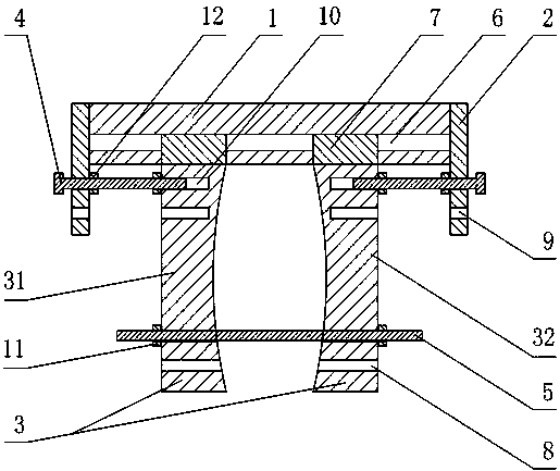
[0021] Such as figure 1 As shown, the outdoor AP embraces the fixer, including a connecting plate 1, a side plate 2, a splint 3, an adjusting bolt 4 and a positioning screw 5, the side plate 2 includes a left side plate and a right side plate, and the splint 3 includes a left splint 31 and a right splint 32, the adjusting bolt 4 includes a left adjusting bolt and a right adjusting bolt, the left side plate and the right side plate are respectively connected to the left and right ends of the connecting plate 1, and the lower end surface of the connecting plate 1 is provided with a small opening The chute 6 with a large inner cavity, the left splint 31 and the right splint 32 are all provided with a convex strip 7 that is compatible with the opening of the chute 6 and the inner cavity, and the convex strip 7 is inserted in the chute 6, so that Both the left splint 31 and the right splint 32 are provided with a first threaded hole 8 relative to the other end of the protruding str...
Embodiment 2
[0025] This embodiment makes the following further limitations on the basis of Embodiment 1: the left splint 31 and the right splint 32 are provided with at least two convex lines 7, and the lower end surface of the connecting plate 1 is provided with the convex lines. 7 fit the chute 6. In this embodiment, the position of the slide groove 6 corresponds to the position of the convex strip 7 . When the splint 3 slides on the connecting plate 1, in order to maintain the stability of the relative movement between the convex strip 7 and the chute 6, three convex strips 7 can be set on the splint 3, which are respectively located at the two ends and the middle of the splint 3 end face.
Embodiment 3
[0027] This embodiment makes the following further limitations on the basis of Embodiment 1: the left splint 31 and the right splint 32 are provided with at least two third threaded holes 10, and the left splint is provided with the left splint. The third threaded hole 10 on 31 is adapted to the second threaded hole 9, and the second threaded hole 9 adapted to the third threaded hole 10 on the right clamping plate 32 is provided on the right side plate. In order to ensure that the adjusting bolt 4 can evenly act on the splint 3 and further strengthen the fixing effect of the adjusting bolt 4 on the position of the splint 3 , the third threaded hole 10 can be arranged on the splint 3 as a mirror image. For example, the third threaded hole 10 can be arranged on the left end surface of the left splint 31 in a mirror image along the transverse direction and the longitudinal direction respectively.
PUM
 Abstract
Description
Claims
Application Information
 - R&D
- Intellectual Property
- Life Sciences
- Materials
- Tech Scout
- Unparalleled Data Quality
- Higher Quality Content
- 60% Fewer Hallucinations
Browse by: Latest US Patents, China's latest patents, Technical Efficacy Thesaurus, Application Domain, Technology Topic, Popular Technical Reports.
© 2025 PatSnap. All rights reserved.Legal|Privacy policy|Modern Slavery Act Transparency Statement|Sitemap|About US| Contact US: help@patsnap.com

