
A temperature difference electric regulating valve for an air conditioning system and a temperature difference control method thereof

An electric control valve, air conditioning system technology, applied in air conditioning system, control input related to air characteristics, space heating and ventilation control input, etc., can solve the problem of unproposed solutions, increase of pipe network impedance, and unsatisfactory energy-saving effect of water pumps and other problems to achieve the effect of improving hydraulic imbalance, reducing investment costs, and improving hydraulic imbalance.

Active Publication Date: 2017-02-22
中国城市发展规划设计咨询有限公司
View PDF10 Cites 0 Cited by
  • Summary
  • Abstract
  • Description
  • Claims
  • Application Information

AI Technical Summary

Problems solved by technology

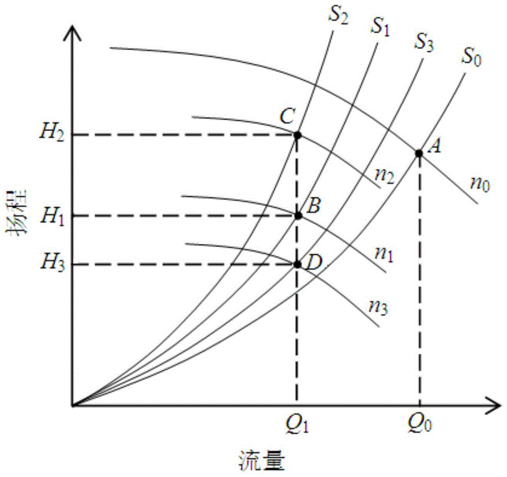
[0004] However, for the existing equipment or methods for improving hydraulic imbalance, the regulating valve of the undercurrent equipment and the regulating valve of the overcurrent equipment are often operated at the same time during the adjustment process. Increase the impedance of the pipe network, that is, the characteristic curve of the pipe network becomes S 2 In the case of the situation, the energy saving effect of the water pump is not ideal
In addition, the existing adjustment methods or equipment are only suitable for air-conditioning systems that adopt constant temperature difference control of chilled water supply and return water mains, and no effective solutions have been proposed for air-conditioning systems that use variable temperature difference control of chilled water supply and return water mains

Method used


Image

  • A temperature difference electric regulating valve for an air conditioning system and a temperature difference control method thereof
  • A temperature difference electric regulating valve for an air conditioning system and a temperature difference control method thereof
  • A temperature difference electric regulating valve for an air conditioning system and a temperature difference control method thereof

Examples


Embodiment Construction

[0018] The technical solutions of the present invention will be further described in detail below in conjunction with the accompanying drawings and embodiments.

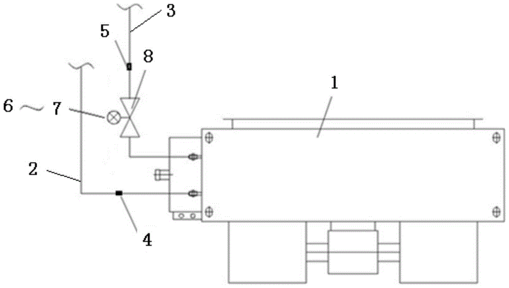
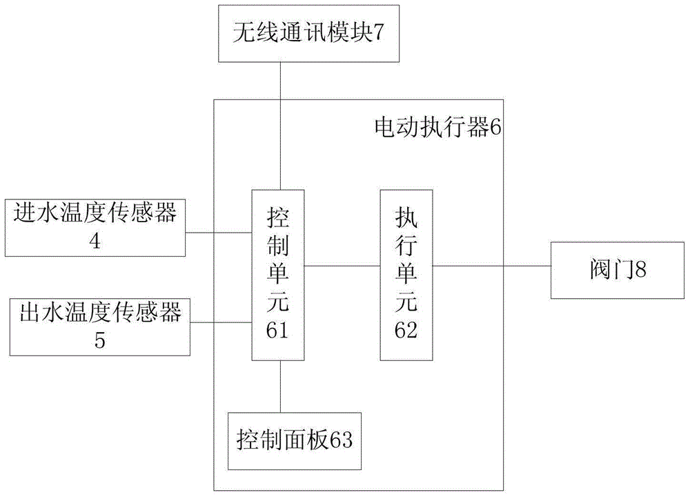
[0019] Such as figure 2 , image 3 As shown, the water inlet of the end fan coil unit 1 is connected to the water inlet pipe 2 , and the water outlet of the end fan coil unit 1 is connected to the water outlet pipe 3 . The temperature difference electric regulating valve of the air conditioning system of the present invention includes an inlet water temperature sensor 4 , an outlet water temperature sensor 5 , an electric actuator 6 , a wireless communication module 7 and a valve 8 . Among them, the water inlet temperature sensor 4 is set on the water inlet pipe 2 of the end fan coil unit 1; on the water outlet pipe 3 of the end fan coil unit 1, a valve 8 and an outlet water temperature sensor are arranged in sequence near the end fan coil unit 1 5. The water inlet temperature sensor 4, the water outlet temperatu...


PUM


Abstract

The invention relates to an electric temperature difference control valve of an air-conditioning system and a temperature difference control method of the electric temperature difference control valve. The electric temperature difference control valve arranged in a chilled water system of a central air-conditioning system is characterized by comprising an incoming water temperature sensor, an outgoing water temperature sensor, an electric actuator, a wireless communication module and a valve; the incoming water temperature sensor is arranged on a water incoming pipeline of a tail fan coil; the valve and the outgoing water temperature sensor are sequentially arranged on places, close to the tail fan coil, of a water outgoing pipeline of the tail fan coil; the incoming water temperature sensor, the outgoing water temperature sensor and the wireless communication module are electrically connected with the electric actuator through cables respectively; the valve is mechanically connected with the electric actuator. According to the arrangement, the energy consumption of the water pump is reduced, and the hydraulic disorder problem of the pipe network is solved. Thus the electric temperature difference control valve and the temperature difference control method thereof can be widely applied to the variable-flow air-conditioning chilled water system adopting the temperature difference control.

Description

technical field [0001] The invention relates to an automatic control device and method for hydraulic balance of an air-conditioning system, in particular to an electric temperature difference regulating valve of the air-conditioning system and a temperature difference control method thereof. Background technique [0002] The existing temperature difference variable flow control method (including constant temperature difference variable flow control and variable temperature difference variable flow control) of the chilled water system of centralized air conditioning is suitable for the air conditioning system where the load change rate of each end user is relatively consistent. However, during the adjustment process, when some end users are closed, it will cause different degrees of hydraulic imbalance in the entire pipe network, resulting in a large difference between the actual inlet and outlet water temperature difference of some end equipment and the set temperature differ...

Claims


Application Information

Patent Timeline
Patent Type & Authority Patents(China)
IPC IPC(8): F24F11/02
CPCF24F1/0007F24F11/30F24F11/62F24F11/89F24F2110/00F24F2221/50
Inventor 陈峰陈晓春
Owner 中国城市发展规划设计咨询有限公司
Learn More