LTE (Long Term Evolution) frequency band multi-antenna-array gain compensation method

A technology of array gain and compensation method, which is applied in antenna arrays, antennas, electrical components, etc., can solve the problems of low frequency point gain, unsatisfactory effect, and increased antenna size

Inactive Publication Date: 2015-03-04
WUHAN HONGXIN TELECOMM TECH CO LTD
View PDF9 Cites 5 Cited by
  • Summary
  • Abstract
  • Description
  • Claims
  • Application Information

AI Technical Summary

Problems solved by technology

[0007] For method (1), if the gain is increased by increasing the number of symmetric oscillators participating in the radiation according to the determined array spacing, the size of the antenna will increase significantly; if the number of oscillators in the antenna array remains unchanged, by increasing the If the distance is increased to increase the gain, the effect of gain improvement is not ideal, and grating lobes will appear; if the size of the antenna is kept constant, while increasing the number of vibrators, the distance between the vibrators and the vibrators is appropriately reduced to increase the gain of the antenna array , the isolation index of the antenna may deteriorate. At the same time, due to the increase in the number of oscillators, the original feeding network scheme must be redesigned
[0008] For the method (2), after the number of

Method used


Image

  • LTE (Long Term Evolution) frequency band multi-antenna-array gain compensation method
  • LTE (Long Term Evolution) frequency band multi-antenna-array gain compensation method
  • LTE (Long Term Evolution) frequency band multi-antenna-array gain compensation method

Examples


Embodiment 1

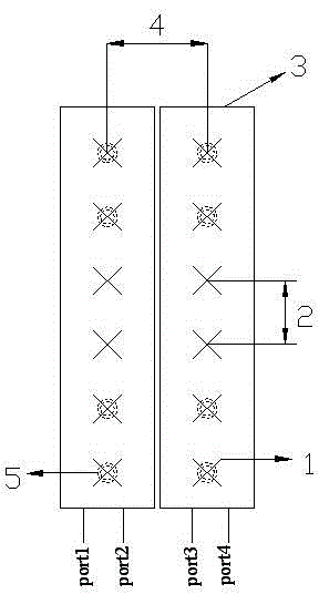
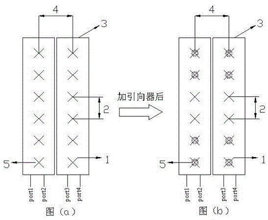
[0050] Embodiment 1, as shown in Figure 2, is the first application scheme of the present invention.

[0051] As for the picture (a), it is an LTE band multi-antenna array that supports 1710-2690MHz frequency band. It consists of two columns of ±45° dual-polarized base station antennas, including four antenna input or output ports, port1, port2, port3, and port4. Each column antenna is composed of six radiating oscillators 1 with a spacing of 2 and a spacing of 4 between columns. Any one of the two columns includes a reflector 3 and a feed network installed behind the reflector. The vibrators are arranged from top to bottom, corresponding to No. 1-1, No. 1-2, No. 1-3, No. 1-4, No. 1-5, and No. 1-6 in the first row, and No. 2-1 in the second row. , No. 2-2, No. 2-3, No. 2-4, No. 2-5, and No. 2-6 oscillators, the power distribution of any row of oscillators is the same, and the specific ratio is P 1 :P 2 :P 3 :P 4 :P 5 :P 6 , and, P 1 2 3 =P 4 >P 5 >P 6 .

[0052] Af...

Embodiment 2

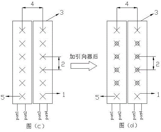
[0056] As shown in Figure 3, it is the second application scheme of the present invention.

[0057] As for the picture (c), it is an LTE band multi-antenna array that supports 1710-2690MHz frequency band. It consists of two columns of ±45° dual-polarized base station antennas, including four antenna input or output ports, port1, port2, port3, and port4. Each column antenna is composed of six radiating oscillators 1 with a spacing of 2 and a spacing of 4 between columns. Any one of the two columns includes a reflector 3 and a feed network installed behind the reflector. The vibrators are arranged from top to bottom, corresponding to No. 1-1, No. 1-2, No. 1-3, No. 1-4, No. 1-5, and No. 1-6 in the first row, and No. 2-1 in the second row. , No. 2-2, No. 2-3, No. 2-4, No. 2-5, and No. 2-6 oscillators, the power distribution of any row of oscillators is the same, and the specific ratio is P 1 :P 2 :P 3 :P 4 :P 5 :P 6 , and, P 1 2 3 =P 4 >P 5 >P 6 .

[0058] After the di...


PUM


Abstract

The invention discloses an LTE (Long Term Evolution) frequency band multi-antenna-array gain compensation method and provides a solution mainly aiming at LTE frequency band multi-antenna-array gain promotion. According to the LTE frequency band multi-antenna-array gain compensation method, a plurality of phase directors are introduced into different positions of arrays according to power distribution ratios of different oscillators under the premise that an original LTE frequency band multi-antenna-array structure (a baffle board, a feed network, the number of arrays, the number of oscillators, the array pitch, the oscillator pitch, a polarization mode and a power distribution ratio) is not changed; every list of the multiple antenna arrays comprises 1 to n phase directors; the phase directors are arranged right above the oscillators; the distance between the phase directors and the oscillators is h; the h is larger than or equal to 0.08lambda and larger than or equal to 0.35lambda; the phase directors of the multiple antenna arrays are cross-shaped or ring-shaped metal pieces; the size of the phase directors is smaller than half lambda; accordingly the gain of the array antenna is improved.

Description

technical field [0001] The invention relates to an LTE frequency band multi-antenna array gain compensation method, which can be widely used in the field of mobile communication base station antennas. Background technique [0002] Antenna gain is used to measure the ability of an antenna to send and receive signals in a specific direction, and it is one of the most important parameters for selecting a base station antenna. Antenna gain is extremely important to the quality of operation of a mobile communication system because it determines the signal level at the edge of the cell. Increasing the gain can increase the coverage of the network in a certain direction, or increase the margin of the received signal level within a certain range. The parameters that characterize the antenna gain are dBd and dBi. dBi is the gain relative to the point source antenna, and the radiation in all directions is uniform; dBd is relative to the gain of the symmetrical dipole antenna, dBi = d...

Claims


Application Information

Patent Timeline
IPC IPC(8): H01Q21/00H01Q19/00H01Q19/10
Inventor 郭继权田宇兴
Owner WUHAN HONGXIN TELECOMM TECH CO LTD
Why Eureka
Try Eureka