
A new energy vehicle and its permanent magnet synchronous motor

A technology of permanent magnet synchronous motor and stator teeth, which is applied to synchronous motors with static armatures and rotating magnets, etc., can solve the problem of low slot full rate and so on.

Active Publication Date: 2017-05-31
CHONGQING CHANGAN AUTOMOBILE CO LTD
View PDF8 Cites 0 Cited by
  • Summary
  • Abstract
  • Description
  • Claims
  • Application Information

AI Technical Summary

Problems solved by technology

[0007] The purpose of the present invention is to provide a permanent magnet synchronous motor, which can solve the problem of low slot fullness

Method used


Image

  • A new energy vehicle and its permanent magnet synchronous motor
  • A new energy vehicle and its permanent magnet synchronous motor
  • A new energy vehicle and its permanent magnet synchronous motor

Examples


Embodiment Construction

[0037] The core of the present invention is to provide a permanent magnet synchronous motor, which can improve the slot fill rate; another core of the present invention is to provide a new energy vehicle including the above permanent magnet synchronous motor.

[0038] In order to enable those skilled in the art to better understand the solution of the present invention, the present invention will be further described in detail below in conjunction with the accompanying drawings and specific embodiments.

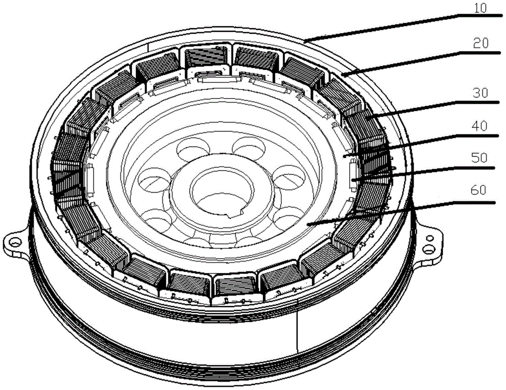
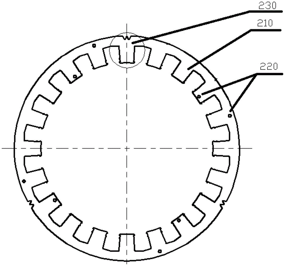
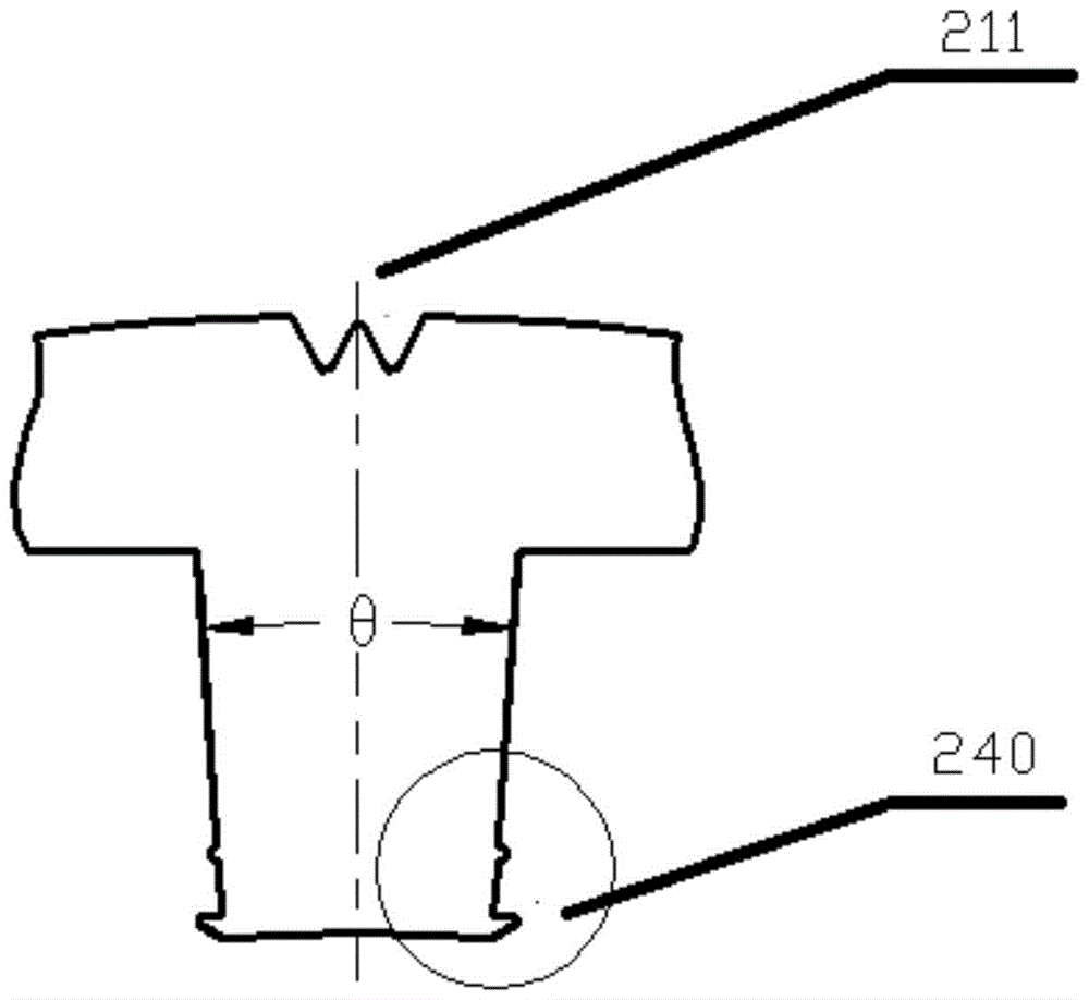
[0039] Please refer to Figure 1 to Figure 15 ; figure 1 It is a schematic diagram of the overall structure of the permanent magnet synchronous motor in the present invention, figure 2 for figure 1 Schematic diagram of the structure of the stator core, image 3 for figure 2 The partially enlarged schematic diagram of the 230 position in Figure 4 for image 3 The partially enlarged schematic diagram of the 240 position in Figure 5 for figure 1 Schematic diagram of ...


PUM


Abstract

The invention discloses a permanent magnet synchronous motor. The permanent magnet synchronous motor comprises a stator core (20) and a stator winding (30) capable of having splicing fit with the stator tooth of the stator core (20), and the stator winding (30) comprises an insulating framework (310) and varnished wire (320) which winds the outer surface of the insulating framework (310). The head face width of the tooth top of the stator tooth is smaller than the head face width of the tooth root part of the stator tooth. Support slide fasteners are arranged on two lateral tooth walls of the tooth top position of the stator tooth, and a limit slide fastener is arranged between each support slide fastener and the tooth root of the stator tooth; limit grooves (317) capable of having splicing fit with the limit slide fasteners are formed in the inner side wall of the stator winding (30). The permanent magnet synchronous motor is capable of improving the groove fullness of the motor to effectively guarantee the torque and power output by the motor.

Description

technical field [0001] The invention relates to the technical field of electric power engineering, in particular to a permanent magnet synchronous motor. The invention also relates to a new energy vehicle with the permanent magnet synchronous motor. Background technique [0002] With the continuous upgrading of my country's automobile industry, the automobile industry is no longer dominated by traditional gasoline vehicles, and new energy vehicles, as a rapidly rising new army, are constantly challenging the status of gasoline vehicles. [0003] As we all know, there are many differences between new energy vehicles and traditional gasoline vehicles; in simple terms, traditional gasoline vehicles use gasoline as the power source, while new energy vehicles use electricity or solar energy as the main source of power. At present, most new energy vehicles use plug-in hybrid power; its key component is the permanent magnet synchronous motor. Therefore, the performance of permane...

Claims


Application Information

Patent Timeline
Patent Type & Authority Patents(China)
IPC IPC(8): H02K21/14
Inventor 卢有君范旭红苏岭张洁陈健贺刚
Owner CHONGQING CHANGAN AUTOMOBILE CO LTD
Learn More