Method for enhancing permanent magnet synchronous motor rotor position detection precision

A technology of rotor position detection and permanent magnet synchronous motor, applied in the control of generator, motor generator control, AC motor control and other directions, can solve the problems of fast turn-on speed, insertion, etc., to eliminate dead time, promote application, improve Effects of stability and accuracy

Active Publication Date: 2015-03-04
NANJING UNIV OF AERONAUTICS & ASTRONAUTICS
View PDF2 Cites 25 Cited by
  • Summary
  • Abstract
  • Description
  • Claims
  • Application Information

AI Technical Summary

Problems solved by technology

[0003] In an ideal three-phase SVPWM voltage source inverter (VSI), the turn-on signals of the upper and lower tubes of the same bridge arm are complementary, but since it takes time to turn on and off the power tube, and the turn-on speed is faster than the turn-off speed, it prevents the straight-through of the upper and lower tubes of the bridge arm , so a dead time must be inserted during the switching action of the power tube

Method used


Image

  • Method for enhancing permanent magnet synchronous motor rotor position detection precision
  • Method for enhancing permanent magnet synchronous motor rotor position detection precision
  • Method for enhancing permanent magnet synchronous motor rotor position detection precision

Examples


Embodiment Construction

[0034] The present invention provides a method for improving the detection accuracy of the rotor position of a permanent magnet synchronous motor with a rotating high-frequency voltage signal injection method. In order to make the purpose of the present invention, the technical solution and the effect clearer and clearer, and refer to the accompanying drawings and give examples to further describe the present invention in detail illustrate. It should be understood that the specific implementations described here are only used to explain the present invention, not to limit the present invention.

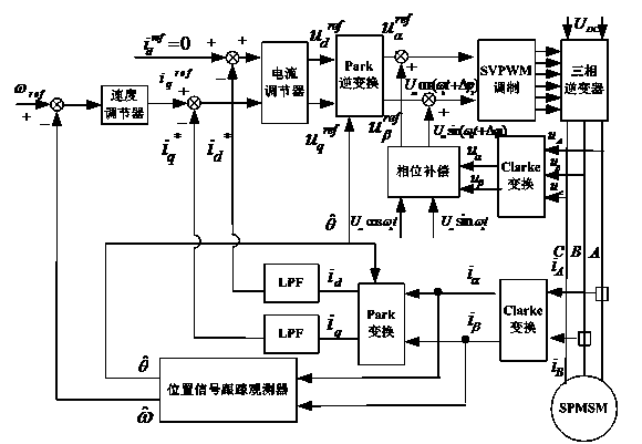
[0035] like figure 1 As shown, the present invention provides a method for improving the detection accuracy of the rotor position of a permanent magnet synchronous motor using a rotating high-frequency voltage signal injection method, which specifically includes the following steps:

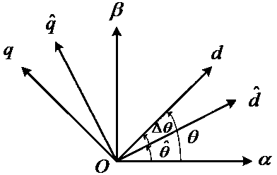
[0036] Step 1: Establish a coordinate system relationship diagram, such as figure 2As shown, d-q i...


PUM


Abstract

The invention discloses a method for enhancing permanent magnet synchronous motor rotor position detection precision. The method comprises the steps that phase closed loop control of a high-frequency injection signal is introduced for phase compensation on the basis of conventional position estimation via a rotating high-frequency voltage signal injection method so that high-frequency signal phase delay generated by inverter dead zone time and IGBT stray capacitance is eliminated and thus the caused position detection error is avoided. The method is easy to realize, position detection precision of the rotating high-frequency voltage signal injection method is effectively enhanced and application range is widened.

Description

technical field [0001] The invention relates to a method for improving the detection accuracy of the rotor position of a permanent magnet synchronous motor, which belongs to the field of motor control. Background technique [0002] At present, the rotor position detection of low-speed and zero-speed permanent magnet synchronous motors mainly adopts two forms of high-frequency signal injection methods: rotation and pulse vibration. The pulse vibration high-frequency signal injection method has the advantages of simple implementation and wide application range. However, Qin Feng pointed out in the article "Research on PMSM Sensorless Control Based on the Concept of Power Electronic System Integration" that from the perspective of system debugging, since the vector control system of the motor constitutes a closed-loop control of the rotor position angle, the pulse vibration high-frequency signal injection method It is sensitive to the parameters of the regulator, how to set the...

Claims


Application Information

Patent Timeline
Patent Type & Authority Applications(China)
IPC IPC(8): H02P21/14H02P21/13H02P25/02
Inventor 王龙周波刘兵李洁倪天恒
Owner NANJING UNIV OF AERONAUTICS & ASTRONAUTICS
Why Eureka
Try Eureka