Oil-water separation device

An oil-water separation device, oil-water mixture technology, applied in separation devices, liquid separation, separation methods, etc., can solve the problems of low treatment efficiency, incompatibility of oil and water, etc., and achieve good results, high-efficiency separation, and easy centralized recovery. Effect

Inactive Publication Date: 2015-03-11
HENAN JINKAI CHEM INVESTMENT HLDG GRP
View PDF4 Cites 10 Cited by
  • Summary
  • Abstract
  • Description
  • Claims
  • Application Information

AI Technical Summary

Problems solved by technology

At present, the primary treatment method of gravity separation is used, which uses the density difference between oil and water and the incompatibility of oil and water to separate oil droplets, suspended solids and water in a static or flowing state, but the treatment efficiency of this method is low

Method used


Image

  • Oil-water separation device

Examples


Embodiment Construction

[0024] The technical scheme of the present invention is described below with specific examples, but protection scope of the present invention is not limited thereto:

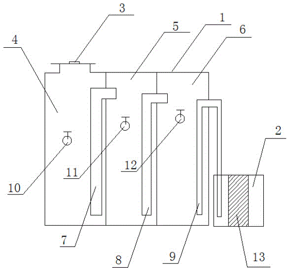
[0025] Such as figure 1 As shown, an oil-water separation device, the main body of the device includes a closed first tank body 1, the top of the first tank body 1 is provided with an oil-water mixture inlet 3, and two partition plates are arranged in the first tank body 1 The first tank body 1 is divided into three compartments, namely the first compartment 4, the second compartment 5 and the third compartment 6, and the first infusion pipeline 7 connecting the two compartments is respectively provided between the adjacent compartments , the second infusion pipeline 8, the third compartment is provided with an output pipeline 9 communicating with the outside of the tank body 1, the entrance of the infusion pipeline 7, 8 and the output pipeline 9 is close to the bottom of the compartment, the infusion pipeline 7...


PUM


Abstract

The invention belongs to the technical field of separation equipment and relates to an oil-water separation device. The main body of the oil-water separation device comprises an enclosed first tank, the top of the first tank is provided with an oil-water mixture inlet, several separator plates are arranged in the first tank and divides the first tank into several compartments, a liquid transport pipe is arranged between each two adjacent compartments and is used for communicating the two compartments. An output pipe communicated with the external environment is arranged in the last compartment. Inlets of the liquid transport pipes and the output pipe are close to the bottoms of the compartments. Outlets of the liquid transport pipes and the output pipe are close to the top of the first tank. The first compartment communicated with the oil-water mixture inlet is provided with a first oil outlet for oil discharge. The opening height of the first oil outlet is larger than the inlet height of the liquid transport pipe in the first compartment. The oil-water separation device has a simple design, a low cost, good oil-water separation effects and high efficiency, is convenient for waste oil centralized recovery and water recovery and recycle, and can be operated conveniently and fast. The oil-water separation device realizes zero discharge of COD in water.

Description

technical field [0001] The invention belongs to the technical field of separation equipment, in particular to an oil-water separation device. Background technique [0002] The urea production plant is equipped with multiple reciprocating compressors and reciprocating plunger pumps. The operation of these equipment requires a lot of oil lubrication and water cooling, and a small part of oil and water leakage is inevitable, which will cause a lot of mixing. Water with oil droplets is produced, which poses a great threat to environmental protection, and must find a way to deal with it. [0003] Taking the compressor as an example, due to the need of oil injection and lubrication during the operation of the compressor, a part of the waste oil and water will be cooled out after compression and cooling between the stages, and this part of the waste oil and water needs to be separated for the compression of the lower stage. The purpose of the final separator is to separate the liq...

Claims


Application Information

Patent Timeline
Patent Type & Authority Applications(China)
IPC IPC(8): B01D17/028B01D17/022
CPCB01D17/0211B01D17/0202B01D2221/14
Inventor 樊进军郭彦刚谢群力李宾祥李波吕丙航王根雷
Owner HENAN JINKAI CHEM INVESTMENT HLDG GRP
Why Eureka
Try Eureka