Chamfer forming tool and forming process thereof

A forming tool and chamfering technology, which is applied in the direction of lathe tools, cutting blades, manufacturing tools, etc., can solve the problems of low processing efficiency, low processing accuracy, cumbersome processing operations, etc., reduce the number of positioning times and improve processing efficiency , the effect of high processing precision

Inactive Publication Date: 2015-03-11
WUHU STERLING STEERING SYST
View PDF7 Cites 4 Cited by
  • Summary
  • Abstract
  • Description
  • Claims
  • Application Information

AI Technical Summary

Problems solved by technology

[0003] The existing chamfering process cannot directly round the front and back of the workpiece positioning hole
The workpiece needs to be positioned twice, the processing accuracy is low, the processing operation is cumbersome, the labor workload of the operator is large, and the processing efficiency is low

Method used


Image

  • Chamfer forming tool and forming process thereof
  • Chamfer forming tool and forming process thereof
  • Chamfer forming tool and forming process thereof

Examples


Embodiment Construction

[0025] The specific implementation manner of the present invention will be described in further detail below by describing the embodiments with reference to the accompanying drawings.

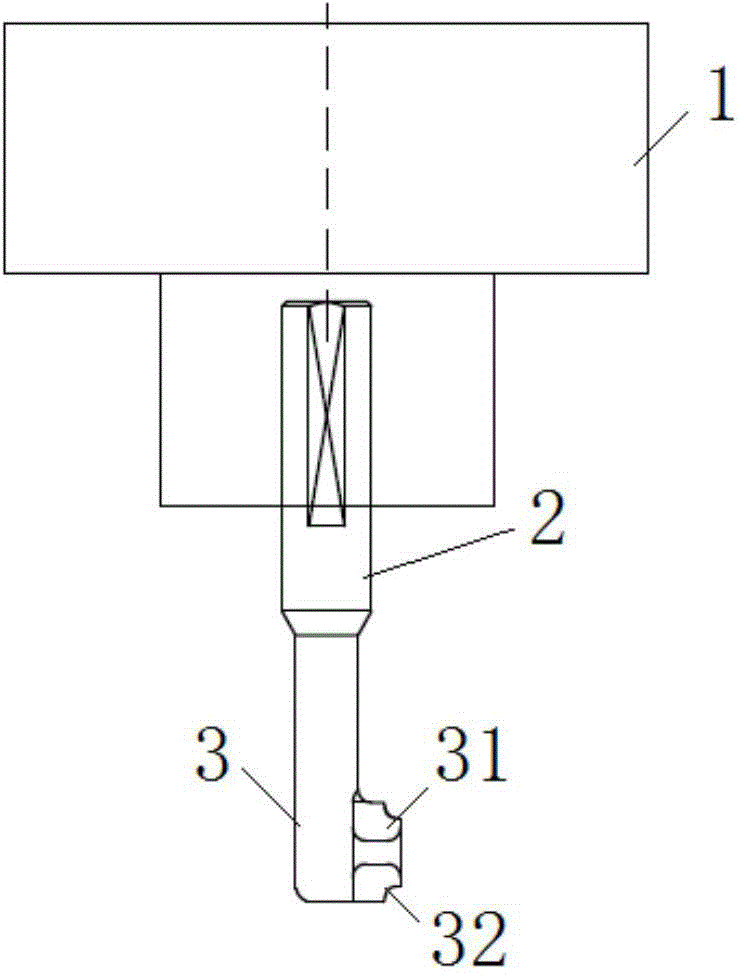
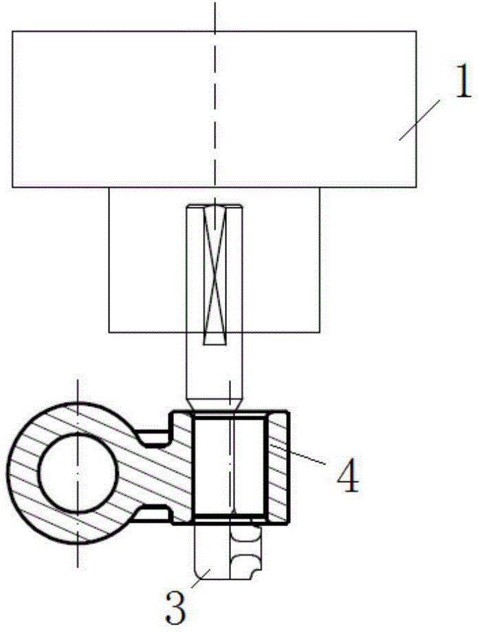
[0026] Such as Figure 1 to Figure 4 As shown, the chamfering forming tool includes a handle 2, a cutter body 3, and a chamfering forming blade, wherein the handle 2 is arranged at one end of the cutter body 3, and the chamfering forming blade is arranged at the other end of the cutter body 3, and the handle and the The tool body is an integral structure, and the tool handle is connected with the main shaft of the machine tool to fix the tool on the processing machine tool.

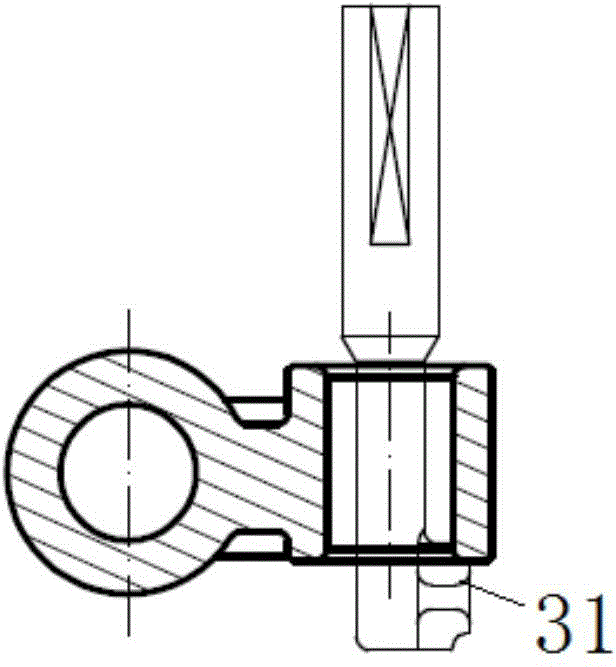
[0027] The chamfering forming blade protrudes and is located at the cutter body 3 sides, and the chamfering forming blade comprises the first chamfering forming blade 31 and the second chamfering forming blade 32 arranged side by side along the cutter body axial direction, the first chamfering forming blade 31 The cutting...


PUM


Abstract

The invention discloses a chamfer forming tool and a forming process thereof. The tool comprises a tool handle, a tool body and chamfer forming blades, wherein the tool handle is positioned at one end of the tool body; the chamfer forming blades are positioned at the other end of the tool body, protrude out of a side face of the tool body and comprise a first chamfer forming blade and a second chamfer forming blade; the edge of the first chamfer forming blade is arranged reverse to the edge of the second chamfer forming blade. Through the tool, rounding treatment can be directly performed on front and back end faces of a workpiece positioning hole, a workpiece is not required to be positioned secondarily, the positioning frequency is reduced, the machining accuracy is high, the operation is easy and convenient, and the machining efficiency is improved.

Description

technical field [0001] The invention relates to the technical field of machining, in particular to a chamfering forming tool and a forming process thereof. Background technique [0002] At present, the rounding processing of both ends of the workpiece positioning hole can be completed through secondary positioning. Firstly, the workpiece is positioned by the positioning fixture. , Loosen the positioning fixture, turn the workpiece over, position and fix it again through the positioning fixture, and round the other end face of the positioning hole of the workpiece. [0003] The existing chamfering processing cannot directly perform rounding processing on the front and back surfaces of the positioning hole of the workpiece. The workpiece needs to be positioned twice, the processing accuracy is low, the processing operation is cumbersome, the labor workload of the operator is large, and the processing efficiency is low. Contents of the invention [0004] Aiming at the defic...

Claims


Application Information

Patent Timeline
Patent Type & Authority Applications(China)
IPC IPC(8): B23B27/06
CPCB23B1/00B23B27/06B23B2200/202B23B2200/3609B23B2220/08
Inventor 吴刚张小刚陈伟范士亮倪申敏徐国平陈林张冬梅马常亮詹拓新吕繁勇陈春红奚琴琴
Owner WUHU STERLING STEERING SYST
Why Eureka
Try Eureka