
Cutter matching method for machining process

A machining and tool technology, applied in the field of tool selection for machining process, can solve problems such as difficulty in discovering the internal connection of information and rules, energy consumption cannot be well controlled, and lack of practicability.

Active Publication Date: 2015-03-11
XI AN JIAOTONG UNIV
View PDF5 Cites 24 Cited by
  • Summary
  • Abstract
  • Description
  • Claims
  • Application Information

AI Technical Summary

Problems solved by technology

[0004] 1) The problem of tool selection involves many contents of production resources and processing technology. With the increase of enterprise processing equipment and product types, the amount of information in this part will become larger and larger, and the relationship between them will become more and more complicated. Traditional methods based on It is difficult for the expert system of production reasoning rules to discover the inherent relationship between information and rules, resulting in a decrease in selection efficiency
[0005] 2) In the process of tool matching, due to the lack of consideration of environmental factors, the energy consumption of the entire machining process cannot be well controlled, resulting in a matching plan that is divorced from actual production and lacks practicability
[0006] Due to the existence of the above two problems, along with the increase in the amount of manufacturing information and the emergence of new manufacturing models, the traditional tool selection method can no longer meet the requirements of actual production, and the tool selection process has become an influence and restriction on the smooth progress of machining. bottleneck problem

Method used


Image

  • Cutter matching method for machining process
  • Cutter matching method for machining process
  • Cutter matching method for machining process

Examples


Embodiment Construction

[0066] The present invention will be further described in detail below in conjunction with the accompanying drawings and specific examples.

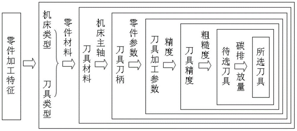
[0067] see figure 1 , the tool matching method for machining process provided by the present invention comprises the following steps:

[0068] 1) Select the matching machine type and tool type according to the processing characteristics of the parts to be processed;

[0069] 2) According to the material type of the part to be machined, in the tool type selected in step 1), select a tool of several kinds of materials, so that the selected tool meets the processing requirements of the part to be machined;

[0070] 3) According to the spindle of the machine tool in the machine tool type selected in step 1), from the tools selected in step 2), select a number of tools whose tool holders are matched with the machine tool spindle;

[0071] 4) According to the specific geometric parameters of the to-be-machined feature of the to-be-machined p...


PUM


Abstract

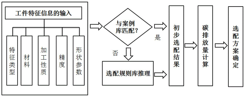
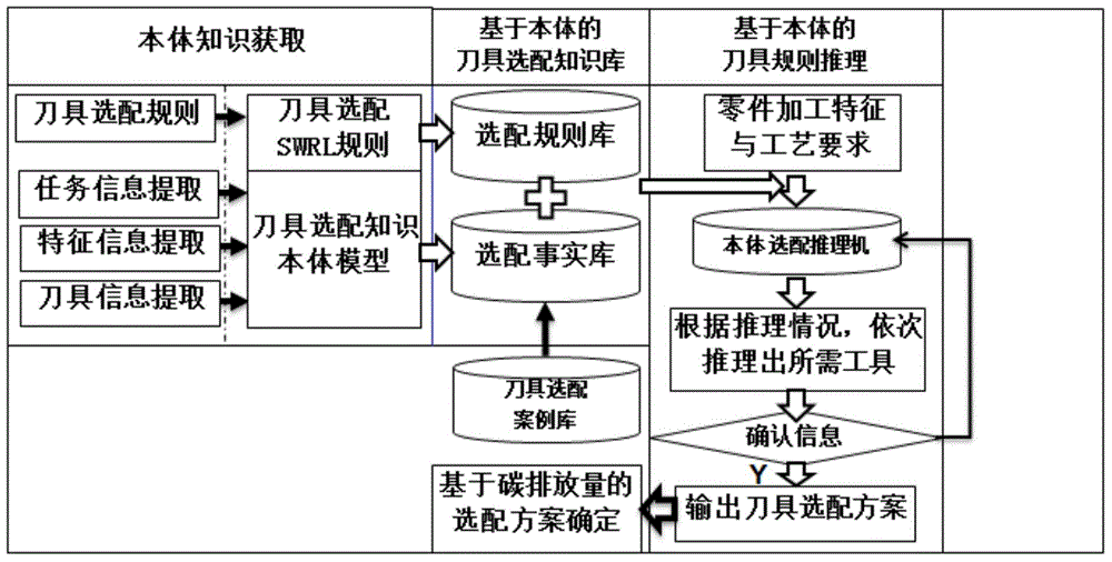
The invention provides a cutter matching method for a machining process. A selective range of cutters to be matched is gradually decreased according to different characteristics of parts to be machined to obtain multiple cutters to be selected satisfying part processing requirements; and then, a final cutter is selected through calculating a carbon emission. The matching method is clear in steps and definite in levels, can reduce the cutter matching complexity, and can improve the reasoning efficiency and the accuracy of cutter matching. As the carbon emission in the machining process is introduced into a cutter matching scheme evaluation as a final selecting standard of the cutters to be matched, on the one hand, the finally matched cutter scheme is closer to actual production requirements to guarantee the matching result practicability, and on the other hand, the control of energy consumption of a workshop production system and the control of the carbon emission in the machining process are realized to a certain extent to improve the green degree of the whole system and to provide the reference for the realization of efficient cutter selection, energy conservation and emission reduction in the machining process.

Description

technical field [0001] The invention belongs to the technical field of advanced manufacturing and automation, and relates to a tool matching method for machining process. Background technique [0002] With the rapid development of my country's equipment manufacturing industry, it has become a pillar industry of the national economy, but at the same time it consumes a lot of social resources, and it has become the main source of current environmental pollution problems and an important object of energy conservation and emission reduction. In order to save resources, reduce energy consumption, and reduce the negative impact on the environment as much as possible in the process of product processing, enterprises pay more and more attention to energy saving and emission reduction in the production process. ) becomes increasingly important. In the modern machining process, the tool has become an important part of the entire manufacturing system that cannot be ignored. It is not ...

Claims


Application Information

Patent Timeline
IPC IPC(8): B23Q3/155
CPCB23Q3/15546
Inventor 周光辉杨翔苗发祥
Owner XI AN JIAOTONG UNIV
Learn More