Mechanical ball screw-type inerter device variable in inerter coefficient

A technology of ball screw type and inertia coefficient, which is applied in the field of inerters, can solve problems such as difficulty in wide application, time-lag limitation, and complex design structure, and achieve the effects of easy manufacturing, improved performance, and reduced impact

Inactive Publication Date: 2015-03-11
JIANGSU UNIV
View PDF9 Cites 17 Cited by
  • Summary
  • Abstract
  • Description
  • Claims
  • Application Information

AI Technical Summary

Problems solved by technology

[0003] Chinese patent application 201110295740.9 discloses a rack-and-pinion inerter that uses a magnetic ferrule to change the inertia coefficient. Chinese patent application 201220667965.2 discloses a hydraulic inerter that combines a solenoid valve to adjust the inertia coefficient. The above two Inerters require additional energy (electric energy) to actively adjust the inertia coefficient. Although the controllability is good, due to the complex design structure and the time-lag limitation of the device, it is widely used in vibration isolation systems such as automobile suspensions. more difficult

Method used


Image

  • Mechanical ball screw-type inerter device variable in inerter coefficient
  • Mechanical ball screw-type inerter device variable in inerter coefficient
  • Mechanical ball screw-type inerter device variable in inerter coefficient

Examples


Embodiment 1

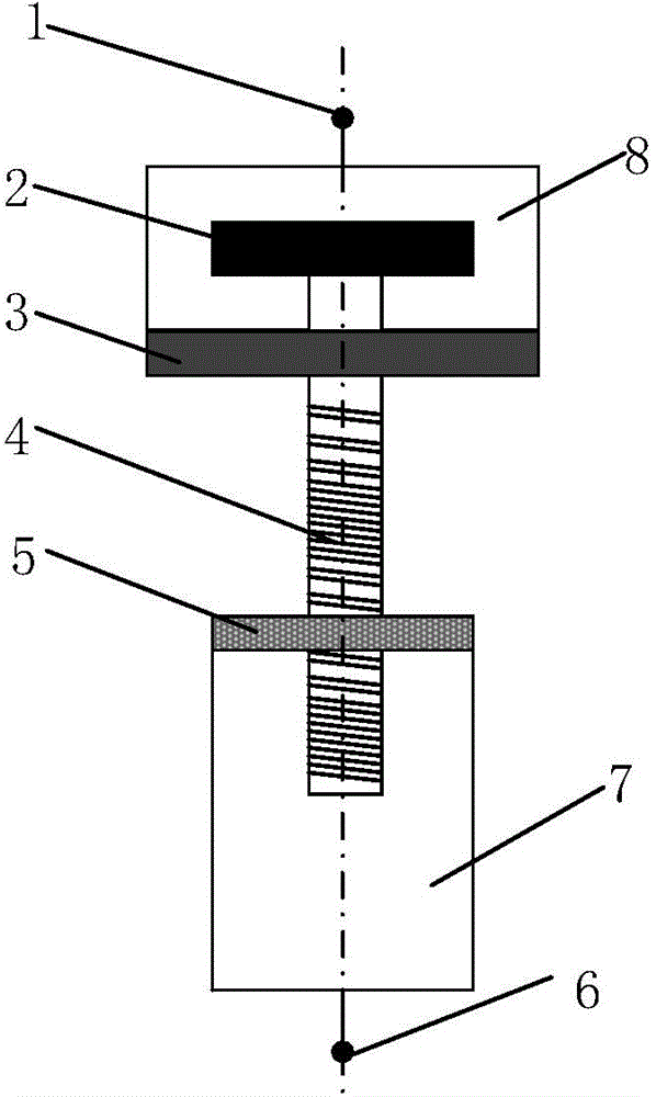
[0028] Such as figure 1 As shown, the ball screw type inerter with mechanical variable inertia coefficient includes upper lug 1, lower lug 6, flywheel 2, flywheel chamber 8, variable lead screw 4, screw nut 5, lead screw Travel room 7. The flywheel 2 is fixed on one end of the variable lead screw 4 through a hinge or a key connection, and is located in the flywheel chamber 8 . The lead screw nut 5 is mounted on the part where the lead screw 4 extends out of the flywheel chamber 8 and is fixedly connected with the upper end surface of the lead screw stroke chamber 7 . The other end of the variable lead screw 4 extends into the screw stroke chamber 7 . The lower part of the flywheel chamber 8 is provided with a limit bearing 3 assembled on the variable lead screw 4 to limit displacement and reduce friction. The upper lug 1 and the lower lug 6 are respectively hinged with the upper end of the flywheel chamber 8 and the lower end of the screw travel chamber 7 .

[0029] As the...

Embodiment 2

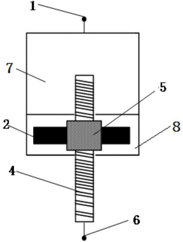
[0045] Such as image 3 As shown, the ball screw type inerter with mechanical variable inertia coefficient includes upper lug 1, lower lug 6, flywheel 2, flywheel chamber 8, variable lead screw 4, screw nut 5, and screw travel chamber 7. The lead screw stroke chamber 7 is located above the flywheel chamber 8, and the upper end surface and the lower end surface of the flywheel chamber 8 are provided with through holes; , the lead screw nut 5 is assembled on the variable lead screw 4; the flywheel 2 is located in the flywheel chamber 8, and one end of the variable lead screw 4 passes through the through hole on the upper end surface of the flywheel chamber 8 and extends to the screw stroke In the chamber 7, the upper end of the screw stroke chamber 7 is hinged with the upper lug 1, and the other end of the variable lead screw 4 passes through the through hole in the lower end surface of the flywheel chamber 8, extending to the outside of the flywheel chamber 8 and the lower lug ...


PUM


Abstract

The invention provides a mechanical ball screw-type inerter device variable in inerter coefficient. The ball screw-type inerter device comprises an upper lifting lug, a lower lifting lug, a flywheel, a flywheel chamber, a variable lead screw, a screw nut and a screw stroke chamber; the flywheel is fixedly arranged at one end of the variable lead screw, and is located in the flywheel chamber; the screw nut is arranged at a part, extending out of the flywheel chamber, of the screw nut, and is fixedly connected with the upper end face of the screw stroke chamber; the other end of the variable lead screw extends into the screw stroke chamber; the upper lifting lug and the lower lifting lug are respectively hinged to the upper end of the flywheel chamber and the lower end of the screw stroke chamber. According to the ball screw-type inerter device provided by the invention, by adopting the variable lead screw, the inerter coefficient is changed by changing the lead of a ball screw; without installing an additional device or utilizing additional energy, and meanwhile, without a complicated and expensive controller, the inerter coefficient of the ball screw-type inerter device can be changed, and the temporary impact on a road surface is retarded, and the inerter device is prevented from being overloaded, so that the performance of a hanger bracket is effectively promoted further.

Description

technical field [0001] The invention relates to an inerter, in particular to a ball screw type inerter with a mechanical variable inertia coefficient. Background technique [0002] Suspension is an important part of buffering and attenuating the input impact of the road surface during the running of the car, which largely determines the driving safety, ride comfort and handling of the car. Suspension has developed from the original traditional passive suspension to the current active and semi-active suspension. However, the application of active and semi-active suspensions is expensive due to the complex structure and the inclusion of electronic control, and is limited due to time lag factors. Therefore, there is still great potential for the research and modification of traditional passive suspensions. [0003] Chinese patent application 201110295740.9 discloses a rack-and-pinion inerter that uses a magnetic ferrule to change the inertia coefficient. Chinese patent applic...

Claims


Application Information

Patent Timeline
Patent Type & Authority Applications(China)
IPC IPC(8): B60G13/04F16F15/31
Inventor 陈龙曹丙坤张孝良
Owner JIANGSU UNIV
Why Eureka
Try Eureka