
A method for quantifying gas distribution in blast furnace throat

A blast furnace throat and furnace throat technology, which is applied in the field of quantifying blast furnace throat gas distribution, can solve problems such as unstable furnace operation, high gas utilization rate, and poor gas utilization, so as to reduce polluting gas emissions and improve utilization rate Level, the effect of improving the technical level of blast furnace

Active Publication Date: 2017-02-01
首钢股份公司迁安钢铁公司
View PDF1 Cites 0 Cited by
  • Summary
  • Abstract
  • Description
  • Claims
  • Application Information

AI Technical Summary

Problems solved by technology

Reasonable gas flow distribution, high gas utilization rate and sufficient ore reduction; unreasonable distribution, poor gas utilization, and some problems of unstable furnace operation

Method used


Image

  • A method for quantifying gas distribution in blast furnace throat
  • A method for quantifying gas distribution in blast furnace throat

Examples


Embodiment 1

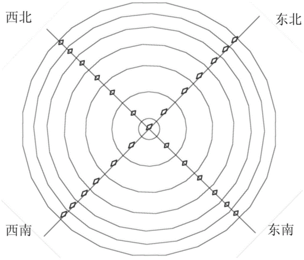
[0071] S1: See attached figure 1 , select the cross temperature measurement model with 7 thermocouples on the cross temperature measurement rod, the directions of the four cross temperature measurement rods are northwest, northeast, southwest and southeast respectively, and establish the furnace throat area according to the cross temperature measurement model airflow distribution model. At this time n=6, the furnace throat area is divided into a circular area GC and 6 annular areas (G1, G2, G3, G4, G5, G6)

[0072] S2: Determine the edge area in the airflow distribution model as G1, the platform area as (G2+G3+G4+G5) and the central area as (GC+G6).

[0073] S3: Calculate bosh gas volume, bosh gas volume = 1.21 x air volume + 2 x oxygen enrichment + humidity x 44.8 x (air volume + oxygen enrichment) / 18000 + coal injection x pulverized coal hydrogen content x 22.4 / 120 .

[0074] S4: Calculation of regional gas volume:

[0075] Regional gas volume WC of circular area GC, W...

Embodiment 2

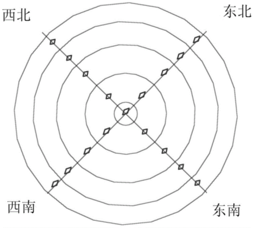
[0092] S1: See attached figure 2 , select the cross temperature measurement model with 5 thermocouples on the cross temperature measurement rod, the directions of the four cross temperature measurement rods are northwest, northeast, southwest and southeast respectively, and establish the furnace throat area according to the cross temperature measurement model airflow distribution model. At this time n=4, the furnace throat area is divided into a circular area GC and 4 annular areas (G1, G2, G3, G4)

[0093] S2: Determine the edge area in the airflow distribution model as G1, the platform area as (G2+G3) and the central area as (GC+G4).

[0094] S3: Calculate bosh gas volume, bosh gas volume = 1.21 x air volume + 2 x oxygen enrichment + humidity x 44.8 x (air volume + oxygen enrichment) / 18000 + coal injection x pulverized coal hydrogen content x 22.4 / 120 .

[0095] S4: Calculation of regional gas volume:

[0096] Regional gas volume WC of circular area GC, WC=bosh gas volu...


PUM


Abstract

The invention relates to a quantitative blast furnace throat gas distribution method including: obtaining a blast furnace throat region; establishing a gas flow distribution model of the blast furnace throat region; according to the gas flow distribution model, determining a blast furnace throat edge region, platform region and central region; according to the formula of furnace bosh gas volume, determining the furnace bosh gas volume; according to the calculation formula of furnace throat region gas volume, determining the edge region edge gas volume Wy, platform region platform gas volume Wz and central region central gas volume Wx; determining edge index, platform index and central index; through the edge index, the platform index and the central index, completing quantitative blast furnace throat gas distribution. The method can accurately evaluate the effect of blast furnace charging system, guides blast furnace charging adjustment; early predicts blast furnace gas state change, prevents the occurrence of major changes in the furnace condition, stabilizes the furnace condition, improves the utilization rate level of blast furnace gas, lowers ironmaking cost, and reduces pollution gas emissions.

Description

technical field [0001] The invention relates to the technical field of blast furnace ironmaking, in particular to a method for quantifying blast furnace throat gas distribution. Background technique [0002] With the advancement of blast furnace smelting technology and the gradual increase of society's requirements for industry in terms of environment and cost, blast furnace production is facing the dual pressure of cost and operating technology. Improving the control level of blast furnace gas flow plays an important role in improving the stability of blast furnace conditions, reducing blast furnace operating costs, and reducing environmental pollution. The distribution of gas flow is related to the temperature distribution in the furnace, the structure of the soft melting zone, the forward flow of the furnace, and the utilization of thermal and chemical energy of the gas, which ultimately affects the output and energy consumption indicators of blast furnace smelting, and h...

Claims


Application Information

Patent Timeline
Patent Type & Authority Patents(China)
IPC IPC(8): C21B5/00
Inventor 许佳马金芳郑敬先解宁强贾军民张海滨刘艳玲龚卫民
Owner 首钢股份公司迁安钢铁公司
Learn More