A device for recovering associated gas in a cluster well group and its recovery method

A recovery method and associated gas technology, applied in earthwork drilling, wellbore/well components, and production fluids, etc., can solve the problems of not forming an economical utilization scale, wasting precious resources, polluting the environment, etc., and achieve social and economic benefits Significant, reducing the effect of flare venting and protecting the ecological environment

Active Publication Date: 2017-10-17
PETROCHINA CO LTD
View PDF6 Cites 1 Cited by
  • Summary
  • Abstract
  • Description
  • Claims
  • Application Information

AI Technical Summary

Problems solved by technology

Usually, in the process of oil production, the associated gas at a single well site is small and scattered, and cannot be used on an economical scale, and most of it is directly discharged or burned, which not only wastes precious resources, but also pollutes the environment

Method used


Image

  • A device for recovering associated gas in a cluster well group and its recovery method
  • A device for recovering associated gas in a cluster well group and its recovery method

Examples


Embodiment 1

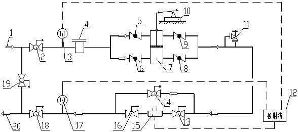
[0020] The associated gas recovery device for the cluster well group provided by the present invention, such as figure 1 As shown, it includes a first ball valve 2, a filter 4, a booster system, and a fifth ball valve 18 connected in sequence from the associated gas input end 1 to the associated gas output end 20, wherein the booster system is composed of an increaser pressure device 7 and four check valves, the filter 4 is connected to the upper and lower air inlets on one side of the booster device 7 through the first check valve 5 and the second check valve 6 respectively, and the other side of the booster device 7 The upper air outlet and the lower air outlet are respectively connected to the fifth ball valve 18 through the third check valve 8 and the fourth check valve 9, and the top end of the piston rod of the supercharging device 7 is hinged with the beam of the pumping unit 10.

[0021] After the associated gas recovery device is connected according to the above-menti...

Embodiment 2

[0034] A flow meter 15 is arranged between the pressurization system of this embodiment and the fifth ball valve 18, the pressurization system is connected to the flow meter 15 through the second ball valve 13 through a pipeline, and the flow meter 15 is output with the associated gas through the fourth ball valve 16 The fifth ball valve 18 at end 20 is connected through pipelines, and the pressurized system is also directly connected to the fifth ball valve 18 through the third ball valve 14 .

[0035] Open the second ball valve 13 and the fourth ball valve 16, close the third ball valve 14, the pressurized associated gas passes through the second ball valve 13, is measured by the flow meter 15, and then is output through the fourth ball valve 16 and the fifth ball valve 18 respectively. , and finally mixed with crude oil to the downstream; when metering is not required, the second ball valve 13 and the fourth ball valve 16 are closed, the third ball valve 14 is opened, and th...

Embodiment 3

[0039] The associated gas supercharging device 7 hinges the cylinder part of the supercharging device 7 with the support of the pumping unit 10 by measuring the upper and lower dead center positions of the oil beam of the pumping unit 10, and the upper part of the piston rod of the supercharging device 7 is connected with the oil pumping unit. The beam of the pumping unit 10 is hinged; the pumping unit 10 drives the piston rod of the device to go up or down through the up and down strokes to suck and compress the gas.


PUM


Abstract

The invention relates to the field of well group associated gas recovery, in particular to a recovery device for cluster well group associated gas and a recovery method thereof. The recovery device comprises a first globe valve, a filter, a pressurizing system and a fifth globe valve, wherein the first globe valve, the filter, the pressurizing system and the fifth globe valve are sequentially connected between an associated gas input end and an associated gas output end through a pipeline; the pressurizing system consists of a pressurizing device and four non-return valves, the filter is connected with two gas inlets, namely an upper gas inlet and a lower gas inlet, of one side of the pressurizing device respectively through a first non-return valve and a second non-return valve, an upper gas outlet and a lower gas outlet of the other side of the pressurizing device are respectively connected to the fifth globe valve through a third non-return valve and a fourth non-return valve, the top end of a piston rod of the pressurizing device is hinged to a wiggle stick of an oil extractor, and a flowmeter is arranged between the pressurizing system and the fifth globe valve. A compressed associated-gas oil-gas mixture is transported to a pressurizing point or block station, and thus, well site associated gas is sufficiently recovered.

Description

technical field [0001] The invention relates to the field of recovery of associated gas in well groups, in particular to a device for recovering associated gas in cluster well groups and a recovery method thereof. Background technique [0002] Generally, when the bottom hole pressure drops below the bubble point pressure, the associated gas will separate from the crude oil. Part of the separated associated gas accumulates in the annular space of the oil casing, forcing the dynamic liquid level of the oil well to drop, reducing the effective production pressure difference of the oil well, and the production capacity. , In severe cases, an "air lock" will occur, making the oil well pump unable to work. [0003] In addition, this part of the associated gas will also cause the phenomenon of "slug flow" during the mixed transportation of oil and gas, which greatly affects the downstream gathering and transportation. The method and the device of the invention solve the bottlenec...

Claims


Application Information

Patent Timeline
Patent Type & Authority Patents(China)
IPC IPC(8): E21B43/00
CPCE21B43/00
Inventor 王勇林罡郭亚红何茂林由方书
Owner PETROCHINA CO LTD
Why Eureka
Try Eureka