Pumping unit indicator diagram liquid production capacity measurement technology

A liquid production and pumping unit technology, which is applied in measurement, wellbore/well components, earth-moving drilling, etc., can solve the problems of low measurement accuracy, difficult operation, manual measurement, etc. Overcome high cost and improve accuracy

Inactive Publication Date: 2015-03-11
BEIJING BOZHONGJIAHE PETRO TECH
View PDF5 Cites 18 Cited by
  • Summary
  • Abstract
  • Description
  • Claims
  • Application Information

AI Technical Summary

Problems solved by technology

[0003] (1) Separator metering technology requires the construction of a metering room, which requires a large investment, manual metering, waste of labor, and covering the surface with points, which cannot reflect the overall liquid production rate;
[0004] (2) Calculation of oil well fluid production by the surface dynamometer chart area method has poor accuracy and poor adaptability. For heavy oil, wax formation, etc., the measurement error of oil well fluid volume is relatively large. In addition, the drift of the sensor also requires the data acquisition accuracy of the equipment. higher, less adaptable;
[0005] (3) The effective stroke method of the surface dynamometer diagram is used to calculate the liquid production rate of the oil well, without considering stroke loss, gas influence, pump leakage, etc., and the calculation error is large
[0006] In the process of realizing the present invention, the inventor found that there are at least defects such as high cost, difficult operation and low measurement accuracy in the prior art

Method used


Image

  • Pumping unit indicator diagram liquid production capacity measurement technology
  • Pumping unit indicator diagram liquid production capacity measurement technology
  • Pumping unit indicator diagram liquid production capacity measurement technology

Examples


Embodiment Construction

[0057] The preferred embodiments of the present invention will be described below in conjunction with the accompanying drawings. It should be understood that the preferred embodiments described here are only used to illustrate and explain the present invention, and are not intended to limit the present invention.

[0058] According to an embodiment of the present invention, such as Figure 1-Figure 13 As shown, the fluid production measurement technology of the pumping unit power diagram method is provided, which can calculate the fluid production of the pumping well in the oil field.

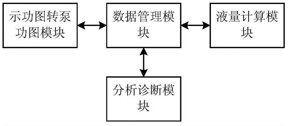
[0059] The technical solution of the present invention mainly includes several large components, namely: a module for converting an indicator diagram to a pump diagram, a data management module, an analysis and diagnosis module, and a liquid volume calculation module.

[0060] Compared with the prior art, the technical solution of the present invention has at least the following characteristics...


PUM


Abstract

The invention discloses a pumping unit indicator diagram liquid production capacity measurement technology. The technology comprises an analysis and diagnosis module, an indicator diagram-to-pump diagram module, a liquid measure calculation module and a data management module, wherein the analysis and diagnosis module is used for calculating each level of rod indicator diagram and pump diagram of a ground indicator diagram by using a diagnostic model; the indicator diagram-to-pump diagram module is used for converting the ground indicator diagram into the pump diagram by using a wave equation; the liquid measure calculation module is used for performing liquid measure calculation based on the ground indicator diagram and production data obtained by the analysis and diagnosis module and each level of rod indicator diagram and pump diagram of the ground indicator diagram calculated by the analysis and diagnosis module; the data management module is used for controlling the liquid measure calculation module to perform liquid measure calculation based on the processing results of the analysis and diagnosis module and the indicator diagram-to-pump diagram module. According to the pumping unit indicator diagram liquid production capacity measurement technology, the defects such as high cost, large operation difficulty and low measurement accuracy in the prior art can be overcome to realize the advantages of low cost, small operation difficulty and high measurement accuracy.

Description

technical field [0001] The invention relates to the technical field of oil field measurement, in particular to the fluid production measurement technology of a pumping unit using a diagram method. Background technique [0002] At present, the liquid volume measurement technology for pumping wells mainly includes: [0003] (1) Separator metering technology requires the construction of a metering room, which requires a large investment, manual metering, waste of labor, and covering the surface with points, which cannot reflect the overall liquid production rate; [0004] (2) Calculation of oil well fluid production by the surface dynamometer chart area method has poor accuracy and poor adaptability. For heavy oil, wax formation, etc., the measurement error of oil well fluid volume is relatively large. In addition, the drift of the sensor also requires the data acquisition accuracy of the equipment. higher, less adaptable; [0005] (3) The effective stroke method of the surfa...

Claims


Application Information

Patent Timeline
Patent Type & Authority Applications(China)
IPC IPC(8): E21B47/00E21B47/008
CPCE21B47/00E21B47/008
Inventor 谢前进杨喜柱王玉臣毛骏逄仁龙
Owner BEIJING BOZHONGJIAHE PETRO TECH
Why Eureka
Try Eureka