
Laminar vibrating shear soil box testing apparatus

A technology of test device and vibration device, which is applied in the direction of vibration test, measuring device, machine/structural component test, etc. It can solve the problems of large gap, small size of shear box, high test cost, etc., and achieves convenient installation and application, and reduces The effect of connecting gaps and ensuring airtightness

Inactive Publication Date: 2015-03-11
HENAN UNIVERSITY OF TECHNOLOGY
View PDF7 Cites 25 Cited by
  • Summary
  • Abstract
  • Description
  • Claims
  • Application Information

AI Technical Summary

Problems solved by technology

[0004] The shortcomings of the devices used in previous studies are: (1) the layered shear box cannot simulate the response characteristics of the soil under vibration; (2) in order to adapt to the shear capacity of the base of the shaking table, the shear box The size is too small; (3) The layer gap between the frame layer and the layer of the shear box is too large, which cannot well simulate the simple shear test of the soil under vibration; (4) The vibration test of the shear box must rely on the shaking table, The test is limited by the vibration capacity of the shaking table and the test cost is too high

Method used


Image

  • Laminar vibrating shear soil box testing apparatus
  • Laminar vibrating shear soil box testing apparatus
  • Laminar vibrating shear soil box testing apparatus

Examples


Embodiment Construction

[0020] The specific implementation of the present invention is described in further detail below in conjunction with accompanying drawing:

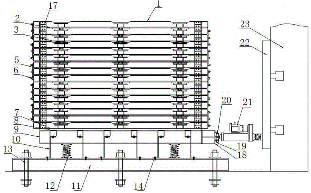
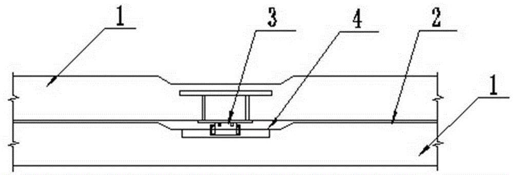
[0021] Such as figure 1 , figure 2 As shown, the layered vibration shear soil box test device includes a shear soil box, a vibration device supporting the shear soil box, and a driving device for driving the vibration device.

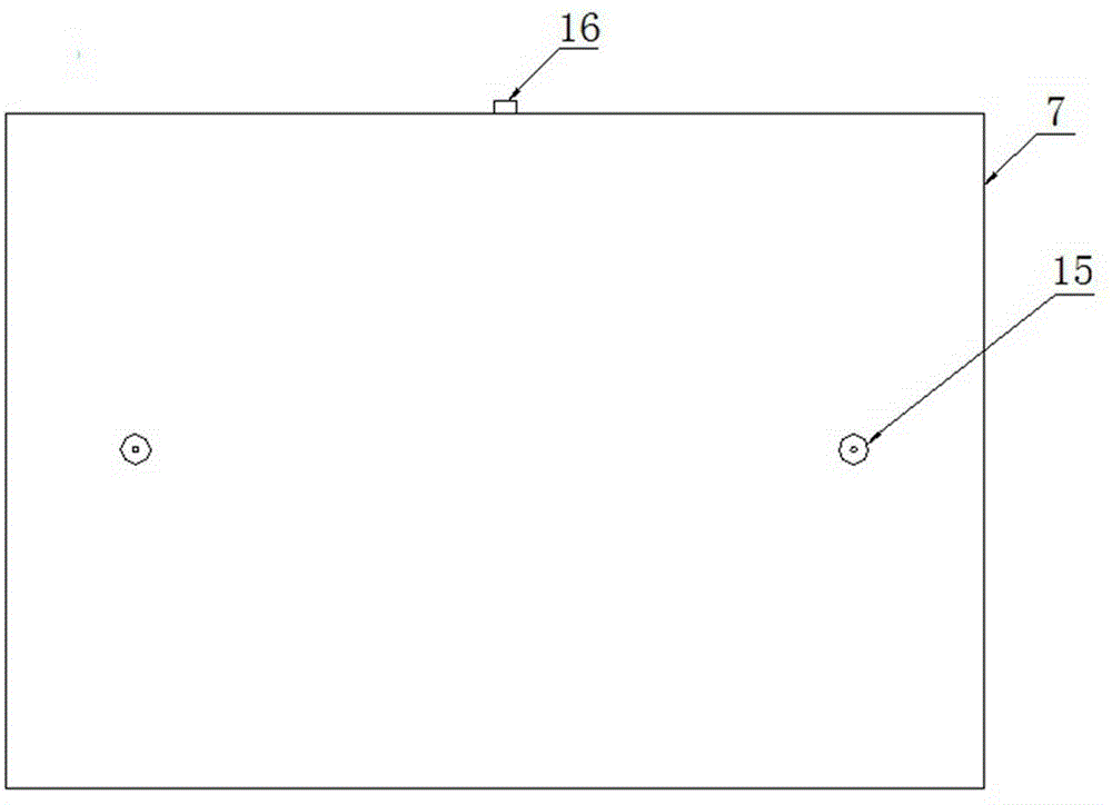
[0022] The main body of the shear soil box is composed of sixteen layers of rectangular frame layers 1 of the same size, each frame layer is 3000mm×2000mm×2000mm, 120mm high, and the gap between layers is 2mm. Six sets of lockable or loosenable sliders 3 and linear guides 4 sets, stacked together (see Figure 4 ), the four corners of the frame layer 1 are riveted with angle steel 17, the sides between the frame layers are connected by a number of rebound leaf springs 5 ​​and hemispherical column hinges 6, the bottom frame layer is welded on the bottom plate 7, and the interior of the shear soil box is installed ...


PUM


Abstract

The invention discloses a laminar vibrating shear soil box testing apparatus. The laminar vibrating shear soil box testing apparatus comprises a shear soil box, a vibrator and a driving device, wherein the shear soil box comprises frame layers; the frame layers are connected with a linear guide rail through a sliding block capable of locking and releasing in the longitudinal direction, and connected with a hemispherical column through a resilient plate spring in the transverse direction and in a hinge manner; the frame layers are placed on a base plate of the vibrator; fold type rubber membranes are arranged inside the shear soil box; folds are inserted among the frame layers and in the gaps between the frame layers and the base plate; the base plate of the vibrator is supported on a floor beam through the plate spring and a spring respectively; base plate holes allowing porous stones to be mounted are formed in the base plate; the bottom beam is fixed on the ground of a laboratory; the driving device comprises an electrical servo actuator arranged on the end face of an I-shaped girder, and a force sensor connected with the electrical servo actuator; the electrical servo actuator is mounted on a reaction wall through a connecting plate. The apparatus can simulate the communication process of shear waves in soil layers with limited thickness in the case of earthquake; the laminar vibrating shear soil box overcomes the limitation of a shear force on a common vibrostand base; the apparatus has the characteristics of being simple in structure, economical in manufacture cost, and convenient to mount and apply.

Description

technical field [0001] The invention relates to a layered shear test device for civil engineering tests, in particular to a layered vibration shear soil box test device. Background technique [0002] Further studies on the amplification effect of infinite soil sites under the action of earthquake vibrations, the dynamic characteristics of soil and the interaction between soil and structures are of great significance in geotechnical earthquake engineering. To study soil properties, such as stress-strain relationships and liquefaction, experimental studies on small numbers of soil samples are often carried out in laboratories using triaxial compressometers, single shear devices, and torsional shear tests under regular or irregular dynamic loads. In these types of tests, stresses and deformations in the soil foundation are significantly affected by boundary conditions. In addition, due to the limitations of the test loading device and sample size, there are differences between...

Claims


Application Information

Patent Timeline
IPC IPC(8): G01M7/04
Inventor 肖昭然朱亮亮周志强吕清显蒋敏敏李梵付志永侯贺营孙亚朋郭柷辉
Owner HENAN UNIVERSITY OF TECHNOLOGY
Learn More