
Pneumatic steering conveyor

A technology for conveyors and conveyor motors, applied in the field of conveyors, which can solve the problems of excessive resistance, inability to rotate flexibly, and the difficulty of steering conveyors to withstand large-weight conveying materials, etc.

Inactive Publication Date: 2018-12-21
WUHU NEW UNIVERSAL ENVIRONMENTAL SCI TECH
View PDF4 Cites 3 Cited by
  • Summary
  • Abstract
  • Description
  • Claims
  • Application Information

AI Technical Summary

Problems solved by technology

[0003] The purpose of the present invention is to provide a pneumatic steering conveyor to solve the defects in the prior art that the steering conveyor is difficult to bear the heavy weight of conveying materials and is easily unable to rotate flexibly due to excessive resistance

Method used


Image

  • Pneumatic steering conveyor
  • Pneumatic steering conveyor
  • Pneumatic steering conveyor

Examples


Embodiment Construction

[0023] With reference to the accompanying drawings, the specific implementation of the present invention will be further described in detail through the description of the embodiments to help those skilled in the art have a more complete, accurate and in-depth understanding of the inventive concept and technical solution of the present invention.

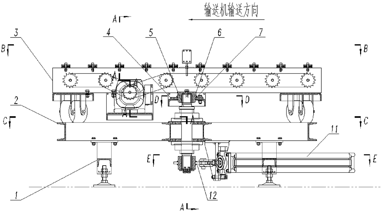
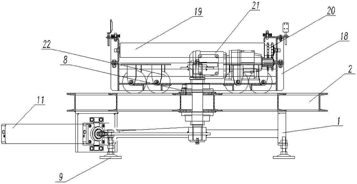
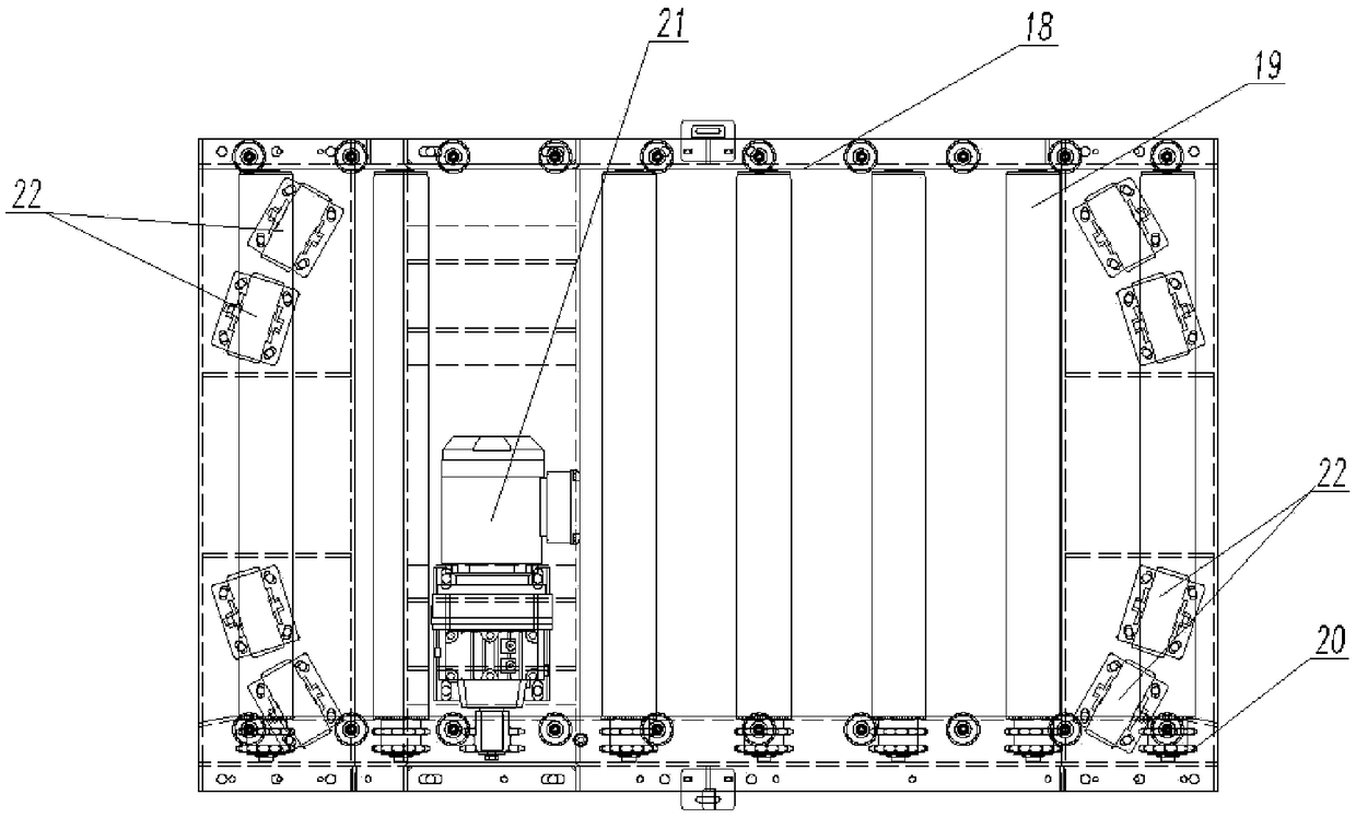
[0024] Such as Figure 1-Figure 9 As shown, the present invention provides a pneumatic steering conveyor. This device can be used for conveying heavy materials and therefore has a relatively large volume. Most of the brackets and frames used are welded by profiles with sufficient strength to ensure load-bearing capacity. The central shaft 5 is made of 40Cr steel as the core shaft, which has good wear resistance, high strength and long service life.

[0025] The pneumatic steering conveyor includes a roller conveying assembly 3, a support assembly and an air cylinder 11. The roller conveying assembly 3 includes a conveying frame 18, a c...


PUM


Abstract

The invention discloses a pneumatic steering conveyor. The pneumatic steering conveyor comprises a support roller conveying module, a bracket module and a cylinder; the support roller conveying modulecomprises a conveying frame, a conveying motor and a support roller; the bracket module comprises a circular frame, a bracket for supporting the circular frame, and a center rotating shaft mounted inthe center of the circular frame through a bearing; the upper end of the center rotating shaft is fixedly connected with the conveying frame; a cylinder rotating shaft is vertically fixed at the ends, with a piston rod, of a cylinder block of the cylinder; a hinge base rotationally connected with a rotating shaft of the cylinder, is fixed on the lower surface of the circular frame; a rotary connecting rod is fixed at the lower end of the center rotating shaft; the end part of the rotary connecting rod is hinged with an extension end of the piston rod; and the piston rod and the rotary connecting rod are perpendicular to the center rotating shaft. During rotating, the cylinder can overcome higher resistance to meet transportation of materials with higher weights.

Description

Technical field [0001] The invention relates to the field of conveyors, in particular to a pneumatic steering conveyor. Background technique [0002] At present, various assembly lines in the manufacturing industry are widely used. In order to change the direction of material movement, we often use steering conveyors, such as labeling, packaging and other processes. Sometimes in order to save space or actual needs, different conveyor tracks are also used. Cross connection, these tracks do not need to run at the same time, so the steering conveyor can be used to control the material conveying direction at the intersection. For example, the utility model with the patent number 201620805943.6 discloses a cylinder connecting rod type aluminum casting steering conveying mechanism, which can realize the steering of the material conveying direction, but the defects of this structure are also obvious. The upper conveying mechanism is supported solely by the rotating shaft. Therefore, th...

Claims


Application Information

Patent Timeline
Patent Type & Authority Applications(China)
IPC IPC(8): B65G41/00B65G47/64
CPCB65G41/002B65G47/648
Inventor 陈亮徐海涛
Owner WUHU NEW UNIVERSAL ENVIRONMENTAL SCI TECH
Learn More