Magnetic levitation spherical motor

A magnetic levitation and spherical motor technology, applied in the direction of electrical components, electromechanical devices, etc., can solve the problems of inability to achieve 360-degree travel, reduce the flexibility of the robot, and limit the rotation angle, and achieve rapid response, simple structure, and convenient steering. Effect

Inactive Publication Date: 2015-03-11
UNIV OF JINAN
View PDF4 Cites 14 Cited by
  • Summary
  • Abstract
  • Description
  • Claims
  • Application Information

AI Technical Summary

Problems solved by technology

And when the car turns, the angle of rotation is limited, and it is impossible to achieve 360-degree travel
[0003] The motors used on the joints of some robots can only realize the movement of one degree of freedom. If complex movements are to be realized, multiple motors are required, which increases the weight of the robot and bloats the structure, which greatly reduces the flexibility of the robot.

Method used


Image

  • Magnetic levitation spherical motor
  • Magnetic levitation spherical motor
  • Magnetic levitation spherical motor

Examples


Embodiment Construction

[0025] Specific embodiments of the present invention will be described below in conjunction with the accompanying drawings.

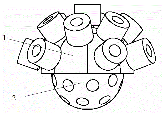
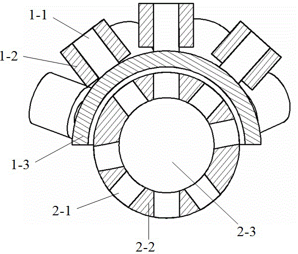
[0026] As shown in the figure, the main embodiment of a spherical motor of the present invention is mainly composed of a stator 1 and a mover 2 matched therewith.

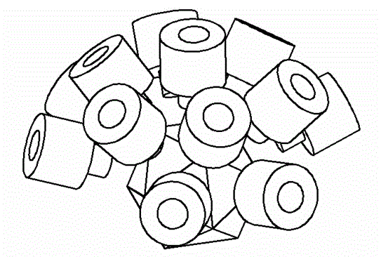
[0027] The mover 2 is a sphere, and the permanent magnet 2-1 is distributed in the sphere of the mover 2. The distribution method is: distributed on all surfaces of the icosahedron 0, and the assembly direction of the magnetic poles points to the center of the mover 2. This The specific embodiment takes the icosahedron as an example, but it is not limited to the icosahedron, and other regular polyhedrons are also applicable. The material of the permanent magnet 2-1 is a rare earth NdFeB permanent magnet. The permanent magnet 2-1 is fixed on the support body 2-3 made of a spherical aluminum plate, and the filling material 2-2 fills the space between the permanent magnet and the support body...


PUM


Abstract

The invention discloses a multi-degree-of-freedom magnetic levitation spherical motor. The magnetic levitation spherical motor comprises a stator structure and a mover structure, wherein a plurality of permanent magnets are uniformly distributed on the spherical surface of the mover structure; the stator structure comprises magnetic levitation coils and thrust coils; a plurality of magnetic levitation coils are arranged on a levitation coil framework in a certain array form; the circumferential thrust coils are uniformly and radially distributed on the circumference of an incomplete spherical surface; and the top thrust coils are uniformly distributed in parallel and vertically on the top of the incomplete spherical surface. Through design of a novel form of structure, the mover can rotate in any direction in a plane. The structure is simple. The magnetic levitation spherical motor has a very good application prospect in multi-degree-of-freedom equipment.

Description

technical field [0001] The invention relates to a multi-degree-of-freedom magnetic levitation spherical motor, which belongs to the technical field of motors. Background technique [0002] At present, the research in motor drive technology is basically one-dimensional or two-dimensional motion, such as: one-dimensional linear motor, one-dimensional rotary motor, two-dimensional planar linear motor, etc. In many cases, the motion of the motor cannot be directly used on machine parts to achieve specific movements. When the power generated by the motor is transmitted to other actuators, some transmission mechanisms need to be added. The addition of transmission mechanisms reduces the overall reliability of the machine and increases energy loss, which is not conducive to the operation of the machine. At the same time, motors with one-dimensional or two-dimensional motion cannot achieve complex motions alone. For example, in a car with a front-engine and rear-wheel drive, the p...

Claims


Application Information

Patent Timeline
Patent Type & Authority Applications(China)
IPC IPC(8): H02K33/18
Inventor 马涛杨学锋李运玺王呈敏蔡喜光闫昂昂顾杰
Owner UNIV OF JINAN
Why Eureka
Try Eureka