Milling machine waste collector

A waste collection and milling machine technology, which is applied to milling machine equipment, milling machine equipment details, maintenance and safety accessories, etc., can solve the problems of low efficiency and poor collection effect of iron filings, so as to prevent iron filings from hurting people's feet and ensure Cleanliness and efficiency-enhancing effects

Inactive Publication Date: 2015-03-18
熊凌聪
View PDF0 Cites 7 Cited by
  • Summary
  • Abstract
  • Description
  • Claims
  • Application Information

AI Technical Summary

Problems solved by technology

[0003] The invention solves the problems of low efficiency of collecting iron filings and poor collection effect by setting up a mil

Method used


Image

  • Milling machine waste collector

Examples


Embodiment 1

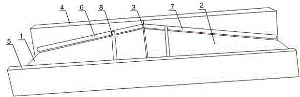
[0023] Such as figure 1 As shown, this embodiment includes a plurality of sequentially connected collecting units, and the collecting units are arranged at the bottom of the external milling machine, and also include a conveying mechanism arranged under the collecting units. A large number of iron chips produced by the milling machine processing of large workpieces. The multiple collection units connected in sequence at the bottom of the milling machine can collect waste from one or more milling machines, which greatly improves the efficiency of the overall processing process of the milling machine; The transmission mechanism under the unit can transfer a small amount of iron filings and engine oil splashed on the ground to the recovery pool for recycling, ensuring a clean operating environment and preventing iron filings from hurting people's feet or preventing workers from slipping and falling. Described collecting unit comprises the left base plate 1 of inclined setting, th...

Embodiment 2

[0026] Such as figure 1 As shown, this embodiment is based on Embodiment 1, and the transmission mechanism includes a groove, a spiral and a fence, the spiral is placed at the bottom of the groove, and the fence is arranged on the groove. When the iron filings and engine oil on the left bottom plate 1 or right bottom plate 2 flow into the groove, the screw installed in the groove is driven, and the iron filings or engine oil start to move in a fixed direction under the drive of the screw blade until Arriving in the recovery pool specially for iron filings, it solves the problem that the remaining iron filings are difficult to clean up; when the screw is driven, there is also a fence above the groove, which can ensure the safety of personnel and avoid safety problems caused by falling into the groove.

Embodiment 3

[0028] Such as figure 1 As shown, this embodiment is based on Embodiment 1, and the angle formed between the left bottom plate 1 and the right bottom plate 2 is 120° to 150°. Within the angle range of 120-150°, the operator can quickly collect iron filings and engine oil by using the inclined plane. When it is higher than the range of 120-150°, the inclination of the left bottom plate 1 and the right bottom plate 2 is not obvious, and the iron filings and engine oil slide down slowly during collection, and the collection efficiency is low; when it is lower than the range of 120-150°, the generated iron filings and Engine oil is easy to be scattered directly on the ground, which is not conducive to collection.

[0029]The cleaning mechanism 8 includes a cleaning rod and bristles arranged on the cleaning rod, and the length of the cleaning rod is equal to the width of the left bottom plate 1 and the right bottom plate 2 . The cleaning rod is slidably arranged on the slideway A...


PUM

PropertyMeasurementUnit
Angleaaaaaaaaaa

Abstract

The invention discloses a milling machine waste collector which comprises a plurality of collecting units connected with one another in sequence and a conveying mechanism arranged under the collecting units, wherein the collecting units are arranged at the bottom of an external milling machine. For a large quantity of scrap iron produced by milling machine machining of large workpieces, waste of one or multiple milling machines can be collected in a concentrated way by the plurality of connected collecting units arranged at the bottom of the milling machines, so that the efficiency of an integral machining procedure of the milling machine is greatly increased; the conveying mechanism arranged under the collecting units can convey a little quantity of scrap iron and engine oil splattered to the ground to a recycling tank for recycling, so as to keep the cleanness of an operation environment, prevent the scrap iron from stabbing the human feet or prevent workers from slipping and falling down.

Description

technical field [0001] The invention relates to the field of mechanical processing, in particular to a milling machine waste collector. Background technique [0002] Compared with the horizontal milling machine, the main difference between the vertical milling machine and the horizontal milling machine is that the spindle is arranged vertically. In addition to the different spindle layout, the workbench can be lifted up and down. The milling cutter used for the vertical milling machine is relatively flexible and has a wide range of applications. , Machine clip cutter head, drill bit for keyway milling, plane milling, boring and other processes. After the processing of the large milling machine is completed, a lot of iron filings or engine oil will be generated on the plane at the bottom of the milling machine. If it is not handled in time, when the accumulation is too large, it is easy to cause the iron filings to hurt the staff's feet or pollute the operating environment. ...

Claims


Application Information

Patent Timeline
IPC IPC(8): B23C9/00B23Q11/00
CPCB23C9/00B23C2230/04B23Q11/0042
Inventor 熊凌聪
Owner 熊凌聪
Why Eureka
Try Eureka