Metal cutting machine

A cutting machine, metal technology, applied in the direction of metal sawing equipment, metal processing machinery parts, metal processing equipment, etc., can solve the problems of reflection, easy to hurt the operator, sparks, etc., to reduce injuries, improve safety and The effect of comfort

Active Publication Date: 2015-03-18
NANJING CHERVON IND
View PDF6 Cites 4 Cited by
  • Summary
  • Abstract
  • Description
  • Claims
  • Application Information

AI Technical Summary

Problems solved by technology

[0003] In order to prevent the sparks from flying around, some operators place the metal cutting machine in the box for cutting, but the sparks splashing on the inner wall of the box will reflect, and the reflected sparks are still not effectively controlled
[0004] In the prior art, some metal cutting machines are equipped with a straight or small arc-shaped spark cover to prevent the sparks from splashing to the rear

Method used


Image

  • Metal cutting machine
  • Metal cutting machine
  • Metal cutting machine

Examples


Embodiment Construction

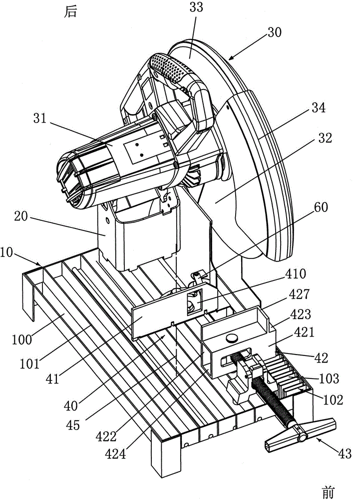
[0013] like figure 1 As shown, the metal cutting machine of the present invention includes a base 10 , a support arm 20 fixedly mounted on the base, and a cutting head 30 pivotally connected to the support arm 20 . The cutting head 30 includes a motor 31 , a blade 32 driven to rotate by the motor 31 , and a fixed shield 33 and a movable shield 34 for covering the blade 32 . The fixed shield 33 is fixedly connected to the cutting head 30 . The cutting head 30 can pivot between the lowest position, which is the working position, where the blade 32 cuts metal, and the highest position, which is the non-working position.

[0014] The base 10 of the metal cutting machine of the present invention is an open base, and the base 10 is provided with a plurality of holes 100 , and the area of ​​the holes 100 accounts for at least 20% of the total area of ​​the upper surface 101 of the base 10 . Such a base has beneficial effects: on the one hand, the sparks that fly to the base 10 gene...


PUM


Abstract

The invention relates to a metal cutting machine. The metal cutting machine comprises a base, a support arm, a cutting head, a clamping device and a spark catcher component, wherein the support arm is fixedly mounted on the base, the cutting head is pivotally connected with the support arm, the clamping device is mounted on the base and comprises a first clamping part close to the support arm and a second clamping part distant from the support arm, and the spark catcher component comprises a first side wall. The first side wall extends backwards from the first clamping part along the direction basically parallel to the plane where a blade is located, the second side wall is opposite to the first side wall, and a gap is formed between the first and second side walls. During cutting, at least a part of blade enters the gap, and the third side wall is connected with the rear end of at least one of the first side wall and the second side wall, so that the rear of the spark catcher component is closed, and the front and the upper of the spark catcher component are at least partially opened. By the spark catcher component of the metal cutting machine, sparks generated during cutting are effectively controlled and splashing of the sparks is avoided.

Description

technical field [0001] The present invention relates to metal cutting machines, and more particularly to spark shield assemblies for metal cutting machines. Background technique [0002] The metal cutting machine will generate a lot of sparks when cutting metal, and the sparks will fly in all directions. The high-temperature sparks will easily burn the human skin or burn the surrounding objects. [0003] In order to prevent the sparks from flying around, some operators place the metal cutting machine in the box for cutting, but the sparks splashing on the inner wall of the box will reflect, and the reflected sparks are still not effectively controlled. [0004] In the prior art, some metal cutting machines are equipped with a straight or small arc-shaped spark cover to prevent the sparks from splashing to the rear of the cutting machine, but the sparks splashing backward will also be reflected after hitting the spark cover. Part of the reflected sparks will fly to the opera...

Claims


Application Information

Patent Timeline
IPC IPC(8): B23D47/02B23D47/04B23D59/00B23Q11/08B23Q11/06B23Q3/06
Inventor 葛锋锋周建舟
Owner NANJING CHERVON IND
Why Eureka
Try Eureka