Clamping fixture

A clamping and clamping technology, which is applied in the direction of clamping devices, clamps, clamps, etc., can solve problems such as hindering the precise positioning of the workpiece pallet and hindering the correct operation of the clamping device

Active Publication Date: 2015-03-18
EROWA
View PDF8 Cites 9 Cited by
  • Summary
  • Abstract
  • Description
  • Claims
  • Application Information

AI Technical Summary

Problems solved by technology

Although such clamping fixtures or devices have a proven track record of success in practice, there is the risk of dirt accumulating on the ring fitting face over time, which prevents precise positioning of the workpiece carrier, especially in Z direction
In addition, dirt can also accumulate in the four clamping devices, which again prevents the correct functioning of each clamping device

Method used


Image

  • Clamping fixture
  • Clamping fixture
  • Clamping fixture

Examples


Embodiment Construction

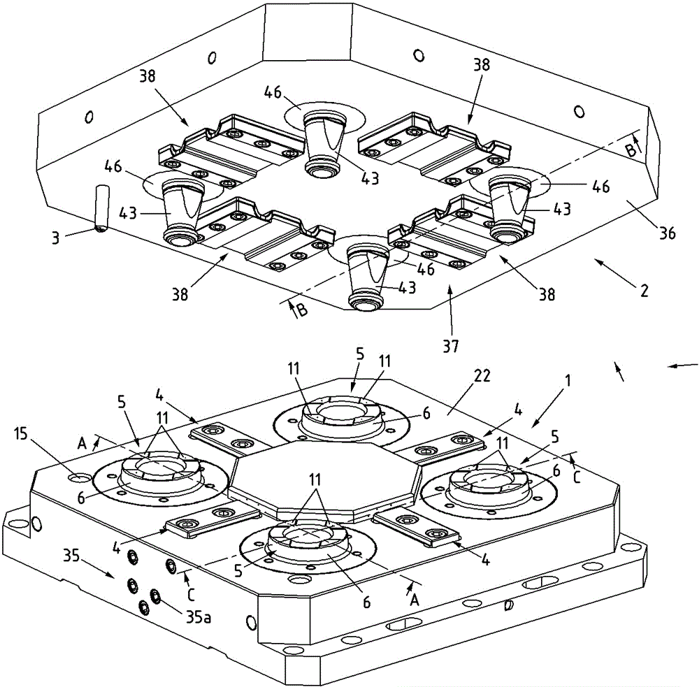
[0019] Reference now figure 1 , the main components of the clamping fixture are illustrated in a perspective view. The clamping fixture comprises a clamping base member 1 and a workpiece pallet 2 fixed in position in the area of ​​the machine tool. As shown, the clamping fixture is used in particular to clamp large and / or heavy workpieces fixedly in place in the work area of ​​a machine tool (eg, a milling machine, a grinding machine or an EDM machine or a lathe). In this context, large and heavy is understood as a workpiece as large as about 500x500x500 mm and weighing several hundred kilograms.

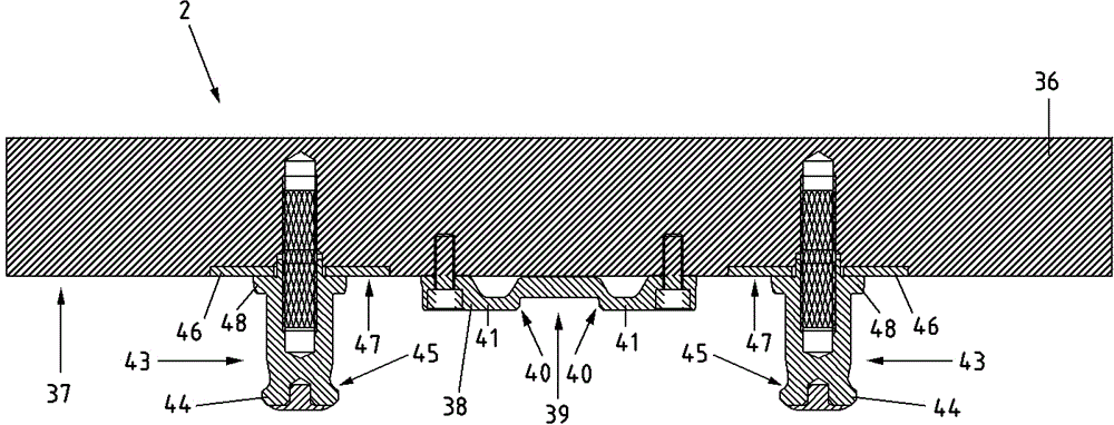
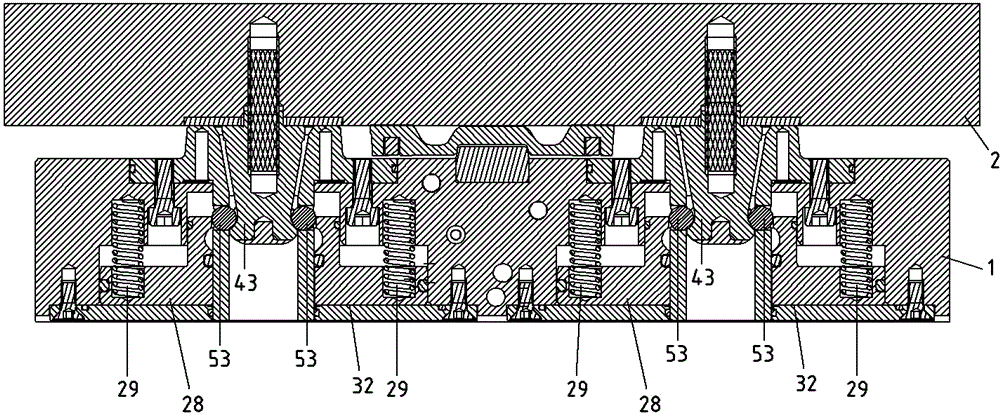
[0020] The clamping base member 1 features a basic element 22 fitted with four clamping devices 5, while the workpiece pallet 2 comprises a main element 36 adapted to four clamping pins 43, which clamp The latch 43 is arranged corresponding to the clamping device and can be fixedly clamped in place in the clamping device 5 . In order to achieve precise positioning of the workpiec...


PUM


Abstract

A clamping fixture comprises a clamping base member (1) and a workpiece pallet (2) for fixedly clamping thereto. The clamping base member (1) features a number of clamping spigots (43) corresponding in number to that of the clamping devices (5) for fixedly clamping in place in each clamping device (5). Arranged on the clamping base member (1) are first centering members (4) which cooperate with the further centering members (38) arranged on the workpiece pallet (2) such that the workpiece pallet (2) is aligned in place when fixedly clamping to the clamping base member in the X-direction and Y-direction. Each clamping device (5) features a clamping socket (6), the top side of which forms the Z-mount for the workpiece pallet (2). The Z-mount of the clamping base member (1) is formed by a plurality of face portions (11) topping each clamping socket (6), and wherein each face portion (11) is provided with at least one outflow port (12) for a cleaning medium. Each clamping socket (6) is provided with a hollow protuberance (10) extending down to the underside of the clamping base member (1).

Description

technical field [0001] The present invention relates to a clamping fixture constructed as set forth in the preamble of claim 1 . Background technique [0002] Such clamping fixtures are put into use for tools, workpieces or workpiece pallets that are defined in clamping position, the clamping base member is usually fixedly mounted on the table of a machine tool or press, while The workpiece pallet is repeatedly releasably seated, precisely positioned on the clamping base member. [0003] Known from EP 0614725 A1 is a device according to the invention for clamping a workpiece in a well-defined position of a work station of a machine tool. Such an apparatus comprises: a clamping base member fixed in a work area of ​​a machine tool; and a workpiece pallet adapted to be placed on the clamping base member and fixed to the clamping base member. In order to align the position of the workpiece pallet with respect to the clamping base member, the latter features a first alignment m...

Claims


Application Information

Patent Timeline
Patent Type & Authority Applications(China)
IPC IPC(8): B23Q3/06B30B15/00
CPCB23Q1/0072B23Q3/06B23B31/1071B23B31/22B23B31/30B23Q1/0081B23Q3/18B23Q7/1426B23Q11/0042B23Q16/04B25B5/061B23Q1/00B23Q3/02B23Q3/067B23Q16/00B23Q2703/02B23Q7/00B23Q7/14B23Q11/005
Inventor H.赫迪格
Owner EROWA
Why Eureka
Try Eureka