Water guide for machine tools

A technology of machine tools and water guide holes, which is applied in the direction of spraying devices, manufacturing tools, metal processing machinery parts, etc., can solve problems such as waste of working time, leakage of processing fluid, cumbersome problems, etc., and achieve the effect of fast and precise adjustment

Inactive Publication Date: 2017-03-01
黄永裕
View PDF5 Cites 0 Cited by
  • Summary
  • Abstract
  • Description
  • Claims
  • Application Information

AI Technical Summary

Problems solved by technology

[0004] Although the existing technology can achieve the effect of adjusting the direction of the water spraying of the water ball, it still has the following deficiencies, please match Figure 12 1. Since the head of the pan-head screw directly presses against the periphery of the water ball, when readjusting the angle, you must first loosen the pan-head screw, and then tighten the pan-head screw again after adjustment to limit the drop-off capacity of the water ball. Holes, such tedious adjustment steps, waste of work time and affect work efficiency
2. The water outlet adjustment range of the water ball ball is limited. If the water ball ball rotates at an excessive angle, the water spray hole of the water ball ball will be covered by the gasket, resulting in the failure of the machining fluid to be sprayed out as scheduled, which will not effectively prevent the tool and cutter from overheating, or Other processing problems occur
3. If the gasket cannot press against the bottom of the step groove tightly, the machining fluid will easily seep out from the gap between the step groove and the gasket, so that the amount and intensity of the machining fluid sprayed cannot achieve the preset effect, which will affect the processing flow and finished product quality
4. In order to allow the water ball 4a to be smoothly installed into the stepped groove 102a, the wall of the stepped groove 102a in the prior art is set as a flat surface, and only the head end of the dish head screw 2a is pressed against the edge of the water ball 4a. position, when the machining fluid is injected, the force of the injection of the machining fluid will cause the water ball 4a to slide towards the notch of the step groove 102a, so that the water ball 4a is easy to slip away from the step groove 102a during the processing

Method used


Image

  • Water guide for machine tools
  • Water guide for machine tools
  • Water guide for machine tools

Examples


no. 1 example

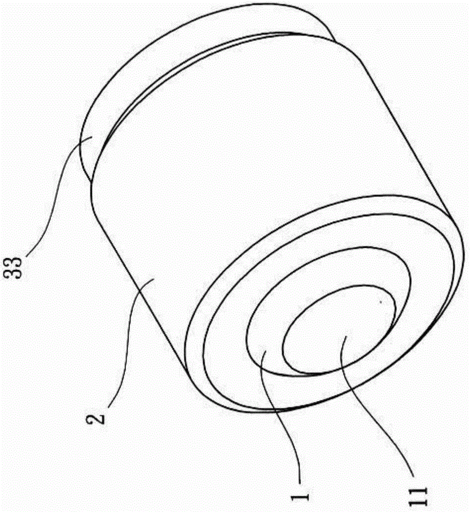
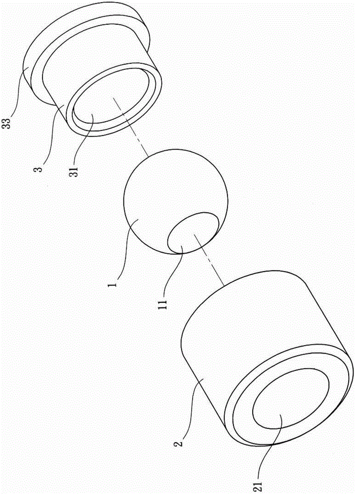
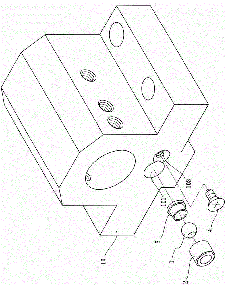
[0044] see Figure 1 to Figure 5 As shown, the present invention is installed on the water guide seat 10. The present invention is a "water guide device for machine tool", which is the first embodiment of the present invention, and it includes a water ball 1, and a water spray hole 11 is formed through it. ; a pressure guide sleeve 2, which is provided with an accommodating hole 21, and the water ball 1 is accommodated in the accommodating hole 21; a leak-proof component 3, which is provided with a water guide hole 31 and a water spray hole 11 and The accommodating hole 21 is connected, and one end of the anti-leakage component 3 is pierced with the accommodating hole 21 and contacts the periphery of the water ball 1, and the anti-leakage component 3 is made of plastic or copper; and a pan head screw 4, which can be screwed on the On the water guide seat 10, and the top end of the dish head screw 4 is pressed against the top of the pressure guide sleeve 2.

[0045] According ...


PUM


Abstract

The invention discloses a water guiding device of a toolroom machine. A water guiding seat is mounted on the toolroom machine. The water guiding device comprises a water ball, a pressure guide sleeve, a leakage-proof component, and a pan-head screw, wherein a water spout hole penetrates through the water ball; an accommodating hole penetrates through the pressure guide sleeve, and the water ball is accommodated in the accommodating hole; a water guiding hole penetrates through the leakage-proof component and is communicated with the accommodating hole, and one end of the leakage-proof component penetrates through the accommodating hole and presses against the edge of the water ball; and the pan-head screw can be locked on a water searching seat, and the head of the pan-head screw presses against the top of the pressure guide sleeve. The water ball can rotate relative to the pressure guide sleeve to adjust the angle corresponding to the water guiding seat of the water spout hole, the liquid can be accurately injected to a target in order to achieve fast and accurate adjustment.

Description

technical field [0001] The present invention mainly relates to the water guiding device of the machine tool, in particular to a water spray hole angle that can quickly adjust the water ball, so that the sprayed liquid can be accurately sprayed to the target object, so as to achieve rapid and precise adjustment. effect. Background technique [0002] Nowadays, lathes or other turning processing technologies are widely used in the processing industry, mainly because lathe processing technology has a variety of cutting functions and can be applied to the processing of various materials. Generally, during the cutting process, there is a gap between the tool and the workpiece It will generate heat due to high-speed friction. If the accumulated temperature is too high, it will easily cause tool wear or workpiece deformation. In order to prevent the above situation from happening, the machine tool will be equipped with a water spray head to spray the machining fluid (water, cutting...

Claims


Application Information

Patent Timeline
Patent Type & Authority Patents(China)
IPC IPC(8): B23Q11/10B05B13/04
CPCB05B15/654B23Q11/10
Inventor 黄永裕
Owner 黄永裕
Why Eureka
Try Eureka