Pressurized leakage-free electromagnetically-controlled gas injection device

An injection device, electromagnetic control technology, applied in the direction of oil supply device, engine control, charging system, etc., can solve the problems of gas injection pressure and injection rate reduction, gas leakage in pipeline structure, and affect the working stability of the gas injection device, etc., to achieve Improved stability, fast gas injection response, improved power and fuel economy

Active Publication Date: 2016-04-20
HARBIN ENG UNIV
View PDF8 Cites 22 Cited by
  • Summary
  • Abstract
  • Description
  • Claims
  • Application Information

AI Technical Summary

Problems solved by technology

[0003] The current in-cylinder direct injection gas injection system mainly controls the movement of the needle valve piston through the internal integrated high-speed solenoid valve to realize the opening and closing of the gas injection valve, which can realize the timing and quantitative control of gas injection, and has good energy saving and reduction However, there are some problems: First, in order to improve the mixing degree of oil and gas in the engine cylinder, the gas injection device has continuously increased requirements on the gas injection pressure. The transmission process of the injection device has high requirements on the pipeline structure and strength, and the gas leakage is serious; secondly, with the movement of the needle valve, the gas leaks upward along the gap between the needle valve coupler, and the leaked gas enters the control chamber, resulting in a decrease in the gas injection pressure and injection rate , seriously affecting the working stability of the jet device

Method used


Image

  • Pressurized leakage-free electromagnetically-controlled gas injection device
  • Pressurized leakage-free electromagnetically-controlled gas injection device
  • Pressurized leakage-free electromagnetically-controlled gas injection device

Examples


Embodiment Construction

[0017] The present invention is described in more detail below in conjunction with accompanying drawing example:

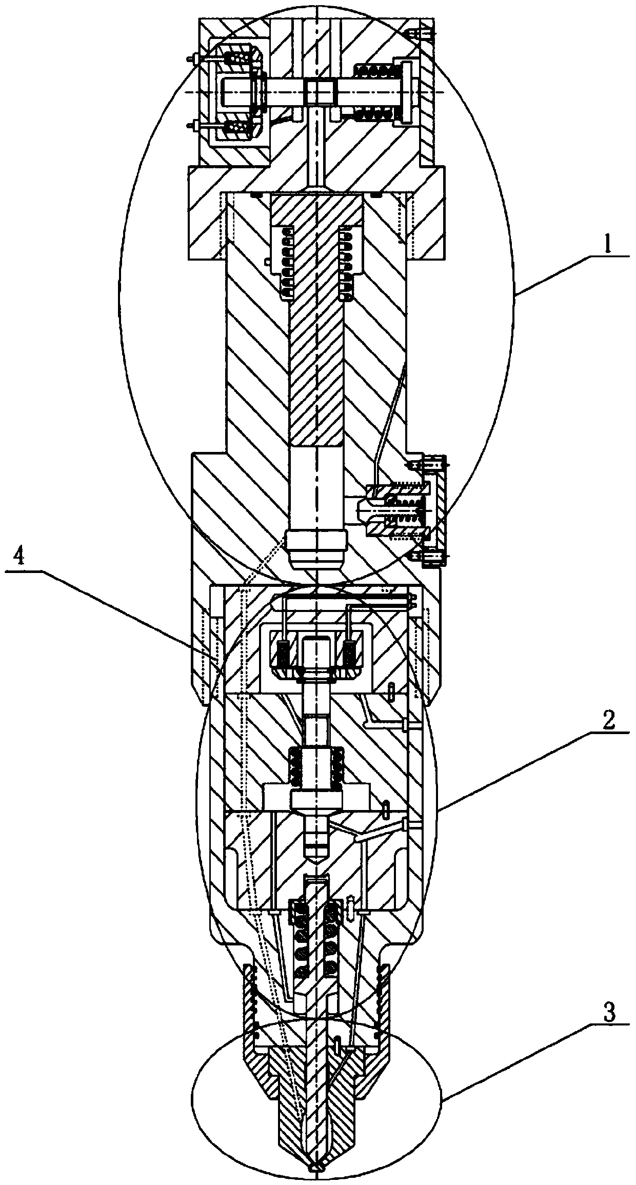
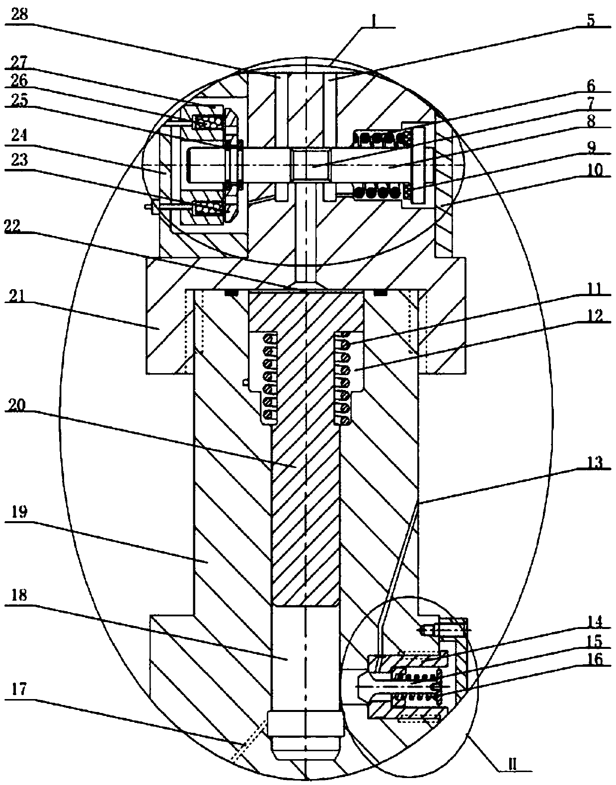
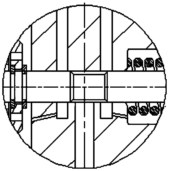
[0018] combine Figure 1~4 , The boosted non-leakage electromagnetic control gas injection device of the present invention is mainly composed of a booster part 1, a control part 2, a nozzle part 3 and an injection device body 4. The booster part 1 mainly includes a booster solenoid valve I, an intake valve II, a booster piston sleeve 19, a booster piston 20, a solenoid valve seat 21, and the like. Wherein, the valve stem 8 of the booster solenoid valve is designed with an annular oil belt 7 , and the solenoid valve seat 21 is designed with a servo oil inlet passage 28 and a servo oil discharge passage 5 . When the boost solenoid valve is not powered, the annular oil belt 7 is connected to the oil discharge passage 5 and the servo oil chamber 22; The intake valve is a one-way valve. When the gas enters the intake valve, the valve stem 15 is opened under the actio...


PUM


Abstract

The invention aims at providing a pressurized leakage-free electromagnetically-controlled gas injection device. The pressurized leakage-free electromagnetically-controlled gas injection device comprises a pressurization part, a control part, a nozzle part and an injection device shell. A pressure is formed in a control cavity by virtue of high-pressure oil to lift a needle valve, response is rapid, and control for a gas injection amount is accurate; a control oil drainage path passes through the upper parts of electromagnetic valves to play a cooling role, thus the stability of the working of the electromagnetic valves is improved; a gas is pressurized by virtue of a pressurization piston, the processes of gas pressurization and gas injection are controlled separately by virtue of two electromagnetic valves, the gas injection process can be flexibly switched between a pressurization mode and a non-pressurization mode, and the pressurization process is slow at first and then fast, thus a variable gas injection rule can be realized, and the requirements of different working conditions of an engine on a gas injection pressure can be met; and in the pressurization part, gas leakage of a pressurization chamber is prevented by virtue of a long sealing coupling and a large oil cavity, a sealing ring belt is arranged between the needle valve and a needle valve base, and a part of control oil is introduced as sealing oil for sealing the gas, thus gas leakage in a needle valve cavity is prevented.

Description

technical field [0001] The invention relates to an engine, specifically a gas injection device for a dual-fuel engine. Background technique [0002] With the continuous consumption of fossil fuels and the increasingly stringent emission regulations of internal combustion engines, the development of engines is facing the dual pressure of energy crisis and environmental pollution. The use of alternative fuels is an effective means to solve both energy problems and environmental pollution. Natural gas and petroleum gas have become the main substitute fuels for internal combustion engines due to their abundant resources, low price, clean combustion, and high calorific value. [0003] The current in-cylinder direct injection gas injection system mainly controls the movement of the needle valve piston through the internal integrated high-speed solenoid valve to realize the opening and closing of the gas injection valve, which can realize the timing and quantitative control of gas ...

Claims


Application Information

Patent Timeline
Patent Type & Authority Applications(China)
IPC IPC(8): F02M21/02F02D19/02
CPCY02T10/30
Inventor 范立云董晓露费红姿李学民彭怀利张孝勇
Owner HARBIN ENG UNIV
Why Eureka
Try Eureka