Swirler Vane, Swirler and Burner Assembly

a swirler and burner technology, applied in the field of swirler vanes, can solve the problems of inefficient injection of fuel, and achieve the effects of accurate control of the fuel being injected, reduced friction resistance of the injection hole and/or the injection feed hole, and improved accuracy of the injection hol

Inactive Publication Date: 2011-05-19
SIEMENS AG
View PDF9 Cites 21 Cited by
  • Summary
  • Abstract
  • Description
  • Claims
  • Application Information

AI Technical Summary

Benefits of technology

[0011]According to a first aspect of the present invention the objective is achieved by a swirler vane for providing fuel, particularly liquid fuel, to a swirling zone of a burner assembly, comprising at least one injection hole for injecting the fuel to the swirling zone of the burner assembly and an injection feed hole passages—particularly comprising a section in form of a gallery—connecting the at least one injection hole with a main fuel feed, whereby the swirler vane or a tip of the swirler vane, where the at least one injection hole is arranged, is being manufactured—i.e. built up—by laser deposition or comprises at least a surface being manufactured by laser deposition.
[0012]The swirler vane or a tip of the swirler vane is built up using laser deposition. One advantage of such a laser deposition grown swirler vane or such a tip of the swirler vane is that the heat treatment during the laser deposition relaxes stresses due to thermal expansion mismatch in the swirler vane, in particular between the swirler vane and the film, since growth occurs at high temperatures, around about 800° C. The design and shape of a swirler vane or a tip of a swirler vane can be influenced very exactly. The swirler itself can be made using conventional machining methods. In order to allow the fuel—particularly liquid fuel—to be injected at the tip of the swirler vane at least a portion of the tip is built up using laser deposition.
[0013]Laser deposition or pulsed laser deposition is a thin film deposition technique where a high power pulsed laser beam is focused inside a vacuum chamber to strike a target of a desired composition. Thereby material is vaporized from the target and deposited as a thin film on the swirler vane and the wall of the injection hole and / or the injection feed hole passages inside the swirler vane, respectively. Such a swirler vane or such a tip of a swirler vane is very heat resistant. The friction resistance of the injection hole and / or the injection feed hole is decreased by a laser depositioned surface. Therefore the fuel can be guided through the injection feed hole passages and / or the injection hole much more accurate. A swirler vane or the tip of a swirler vane which are built up using laser deposition can accurately control the fuel being injected. A swirler vane like that can improve the fuel and air mixing. The fuel can be injected very accurately into the swirler shear layer. Such a swirler vane can reduce the emissions of the burner assembly.
[0014]One swirler vane can have two or more injections holes, if desired.
[0015]Therefore, in a preferred embodiment of the swirler vane, the swirler vane is characterized in that the wall of the at least one injection hole is being manufactured—i.e. built up or formed—by laser deposition. Additional or alternative to that a swirler vane is preferred whereby at least a part of the injection feed hole passages, which end in the at least one injection hole, is being manufactured by laser deposition.
[0016]Preferred is further an embodiment of the swirler vane, whereby the swirler vane is shaped as a pie slice. For example, the swirler vanes can be of a pie slice type with substantially triangular footprints and rectangular side faces and a slightly curved outer surface. The tips of the swirler vane, where the at least one injection hole is arranged, are directed to the swirling zone of the burner assembly.

Problems solved by technology

One disadvantage of the nozzle is that it injects the fuel in a non optimised location due to the mechanical constraints of the system.

Method used


Image

  • Swirler Vane, Swirler and Burner Assembly
  • Swirler Vane, Swirler and Burner Assembly
  • Swirler Vane, Swirler and Burner Assembly

Examples


Embodiment Construction

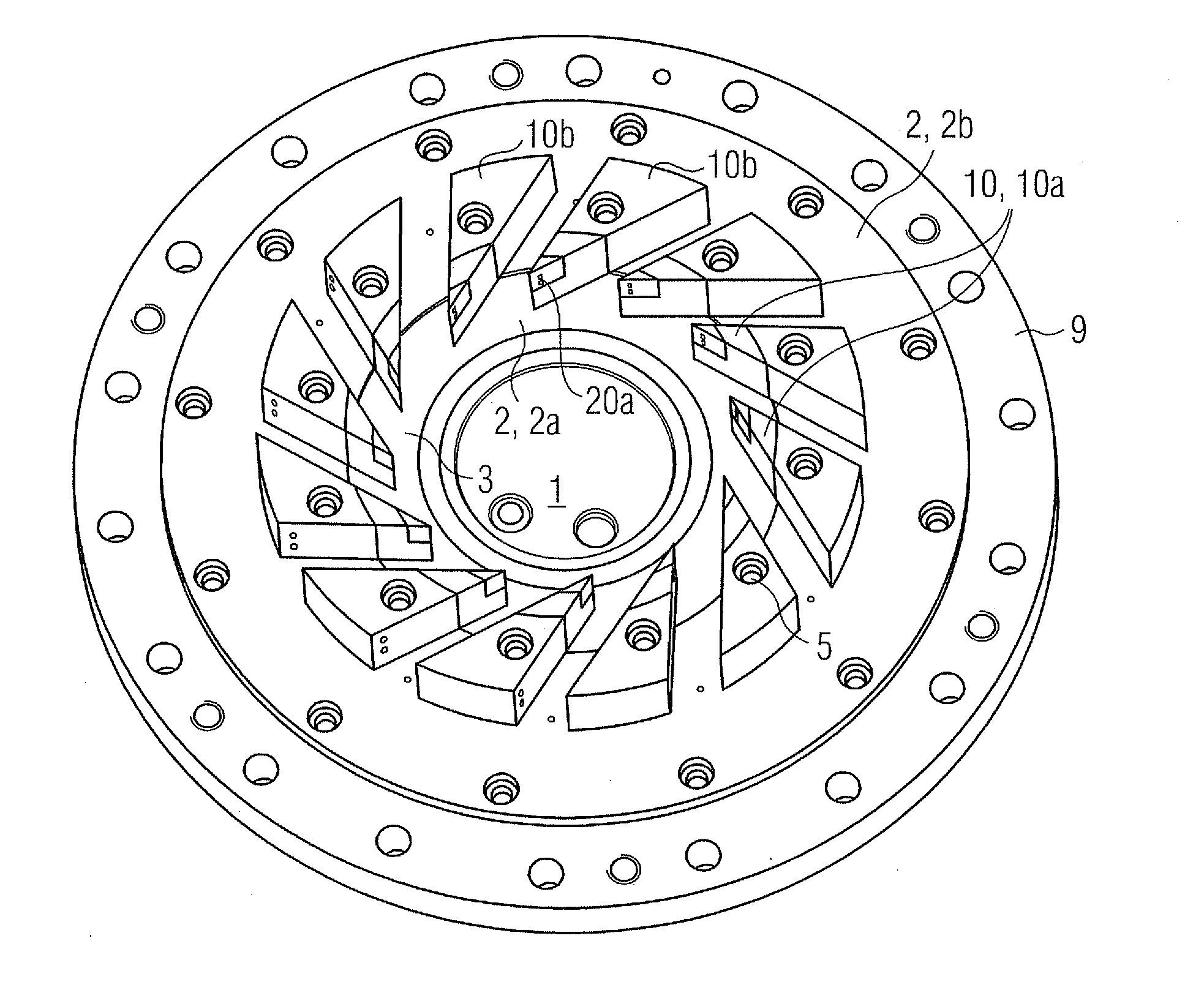
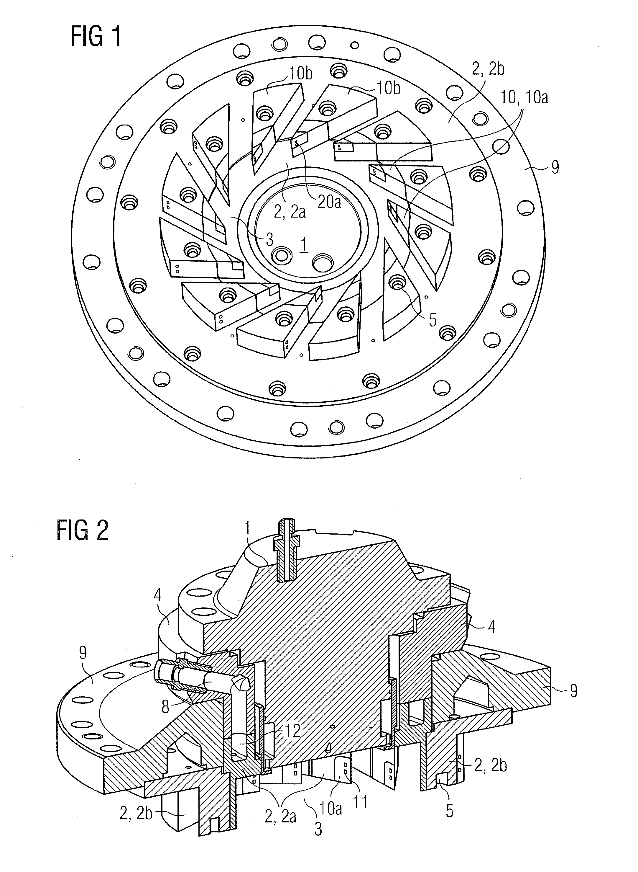
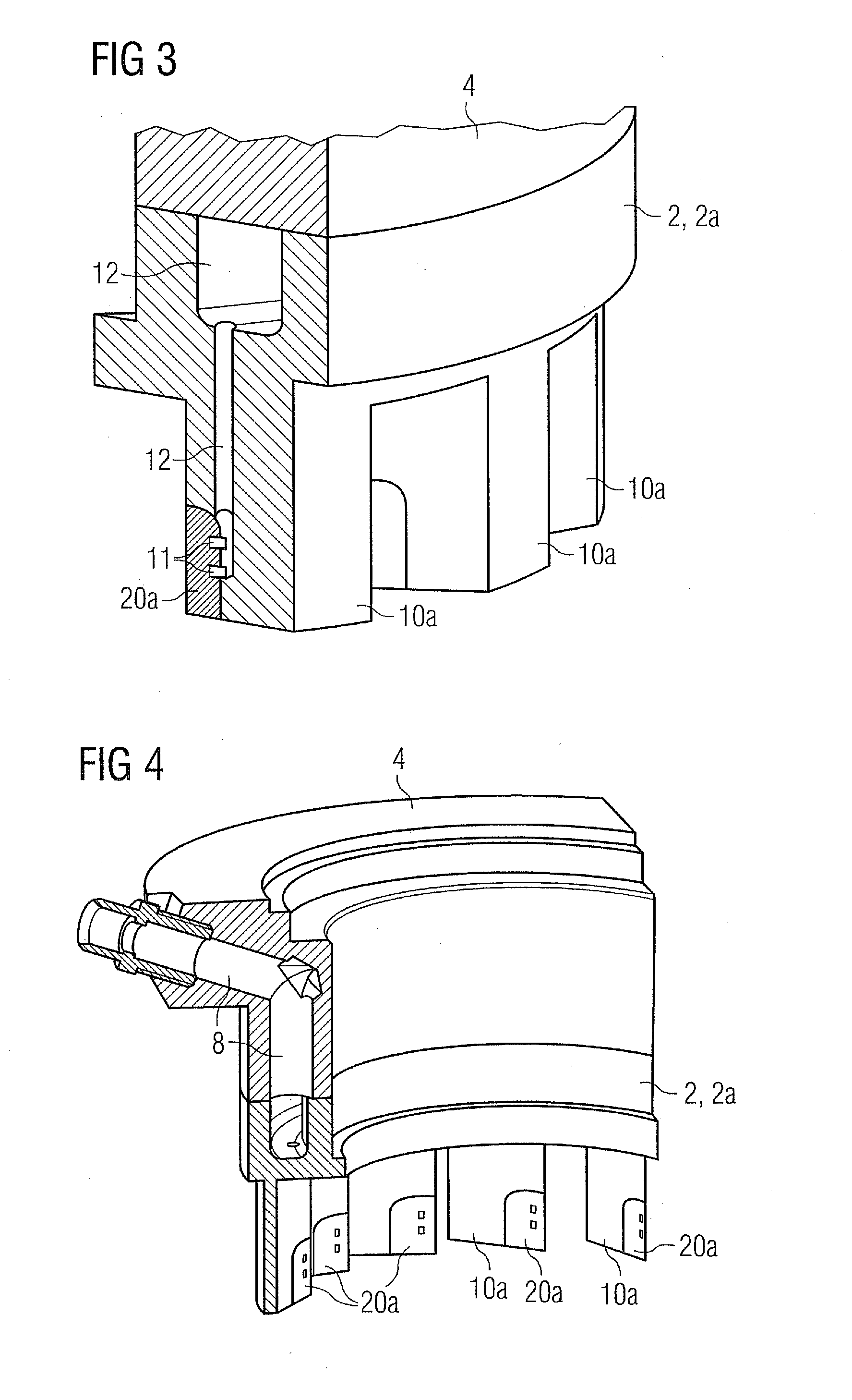
[0036]FIG. 1 shows a perspective view of a possible embodiment of an inventive swirler 2 with inventive swirler vanes 10a and a swirling zone 3 of a burner assembly having a pilot burner 1 in its centre. In this embodiment the swirler 2 is split into two parts, an inner swirler 2a and an outer swirler 2b. The swirler vanes 10a build a first part of overall swirler vanes 10, whereby the swirler vanes 10b build the second part of the overall swirler vanes 10 of the swirler 2. The inner swirler 2a comprises two or more swirler vanes 10a. Each swirler vane 10a provides fuel—preferably liquid fuel but possibly also gaseous fuel—to a swirling zone 3 of the burner assembly. In this embodiment of the swirler 2 the tip 20a of each swirler vane 10a of the inner swirler 2a is built up using laser deposition. The tip 20a as a whole can be manufactured by laser deposition or only the surface of the tip 20a is can be manufactured by laser deposition. One swirler vane 10a of the inner swirler 2a a...


PUM


Abstract

A swirler vane for providing fuel, particularly liquid fuel, to a swirling zone of a burner assembly is provided. The swirler vane includes at least one injection hole for injecting the fuel to the swirling zone of the burner and an injection feed hole passage connecting the at least one injection hole with a main fuel feed. The swirler vane or a tip of the swirler vane, where the at least one injection hole is arranged, is manufactured by laser deposition or includes at least a surface manufactured by laser deposition. A swirler including a plurality of such swirler vanes and a burner assembly including the swirler with such swirler vanes are also provided.

Description

CROSS REFERENCE TO RELATED APPLICATIONS[0001]This application claims priority of European Patent Office application No. 09014417.1 EP Filed Nov. 18, 2009, which is incorporated by reference herein in its entirety.FIELD OF INVENTION[0002]The present invention relates to a swirler vane for providing fuel, particularly liquid fuel, to a swirling zone of a burner assembly, comprising at least one injection hole for injecting the fuel to the swirling zone of the burner and an injection feed hole connecting the at least one injection hole with a main fuel feed. The invention relates further to a swirler, comprising a plurality of swirler vanes, and to a burner assembly, in particular of a gas turbine engine.BACKGROUND OF INVENTION[0003]Air pollution is a worldwide concern and many countries have enacted stricter laws for further limiting the emission of pollutants from gas turbine engines or offer fiscal or other benefits for environmentally sound installations.[0004]Although the prior te...

Claims


Application Information

Patent Timeline
Patent Type & Authority Applications(United States)
IPC IPC(8): F23R3/28F23D14/64
CPCF02C7/22F23C1/08F23C7/004F05D2230/313F23D2900/14021F23R3/14F23R3/286F23C2900/07001
Inventor HEADLAND, PAULSANDERSON, VICTORIA
Owner SIEMENS AG
Why Eureka
Try Eureka