Navigated application guide for targeted spinal drug delivery

a targeted spinal and application guide technology, applied in the field of application guides, can solve the problems of affecting the accuracy of placement and guidance, affecting the accuracy of diagnosis, so as to achieve accurate and stable placement and guidance, and less stable

Active Publication Date: 2015-04-14
BRAINLAB
View PDF8 Cites 21 Cited by
  • Summary
  • Abstract
  • Description
  • Claims
  • Application Information

AI Technical Summary

Benefits of technology

[0017]Thus, the method and apparatus provide an accurate and stable placement and guidance of a specified thin, long and flexible spinal injection needle to a specific area of the lesion. The lesion at the spinal cord can be accurately determined on MR images and can be displayed on a navigation system wherein an MRI data set is superposed on a CT data set of the patient. A software package sold by BrainLAB AG under the trade name VectorVision® spine may be used in conjunction with the method and apparatus.
[0018]Since the application guide can be directly placed to the vertebra nearest to the lesion of the spinal cord, any patient movements can be compensated for and it can be assured that the drug is accurately injected to the intended area during a specified period of time. This eliminates the need for any other placement of the thin and flexible needle, which would lead to a less stable and less accurate application drug delivery.

Problems solved by technology

These procedures typically require a large invasive operation that exposes the patient to a high risk of infection, excessive trauma, blood or fluid loss, post operative pain, scaring, and lengthy recovery time.
Some difficulties relating to surgery on the vertebral column include, for example, micro-movement of the vertebral column and of vertebral bodies to each other (which may be a risk for injuring extremely delicate nerve tissue or the spinal cord).
Another difficulty encountered in vertebral column surgical procedures is the limited operating room space available to the surgeon.
Such space limitations are typically due to relatively large support equipment, such as C-arm X-ray devices, that are in the operating room and used during such procedures.

Method used


Image

  • Navigated application guide for targeted spinal drug delivery
  • Navigated application guide for targeted spinal drug delivery
  • Navigated application guide for targeted spinal drug delivery

Examples


Embodiment Construction

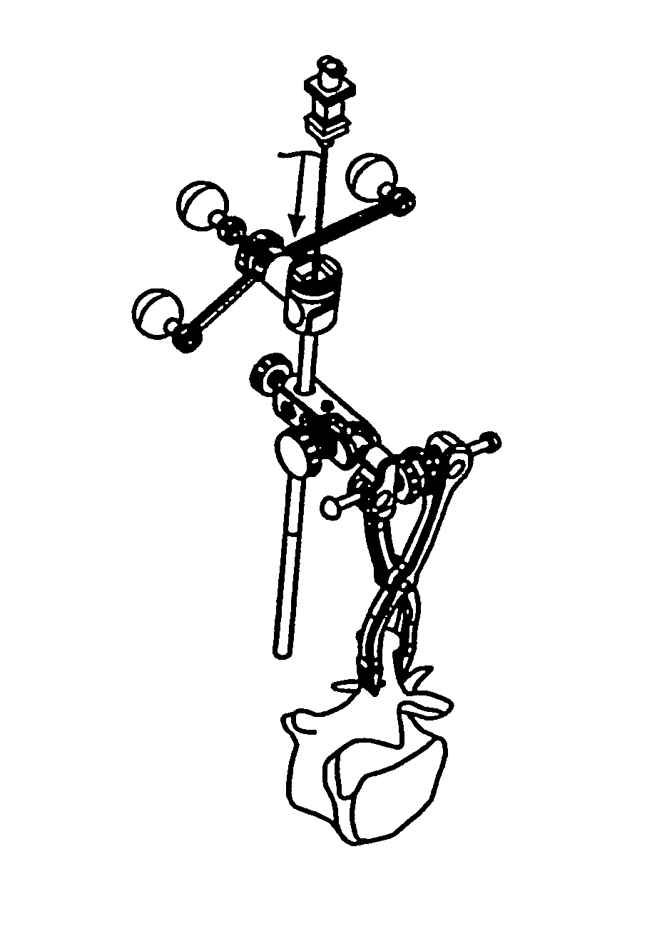
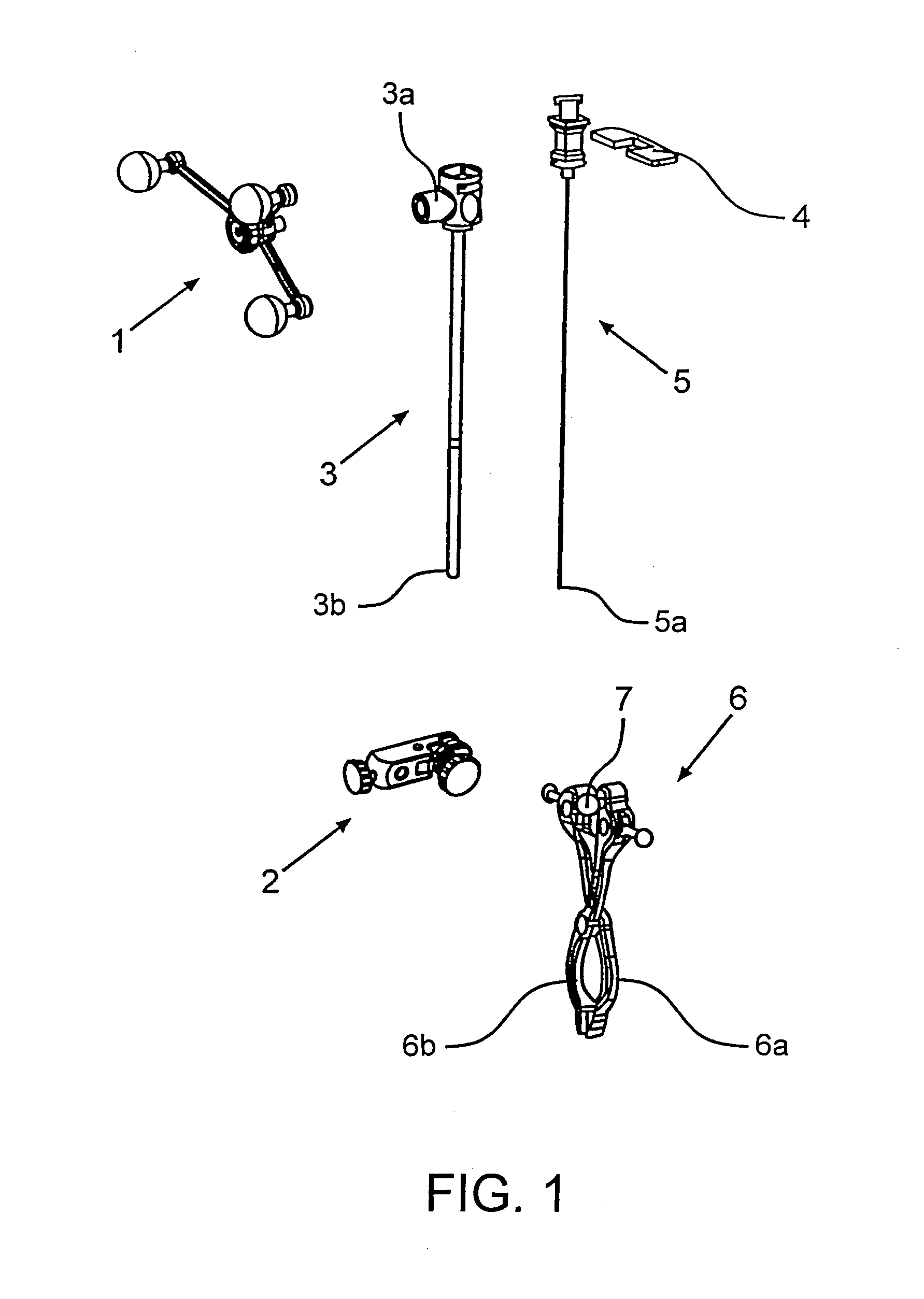
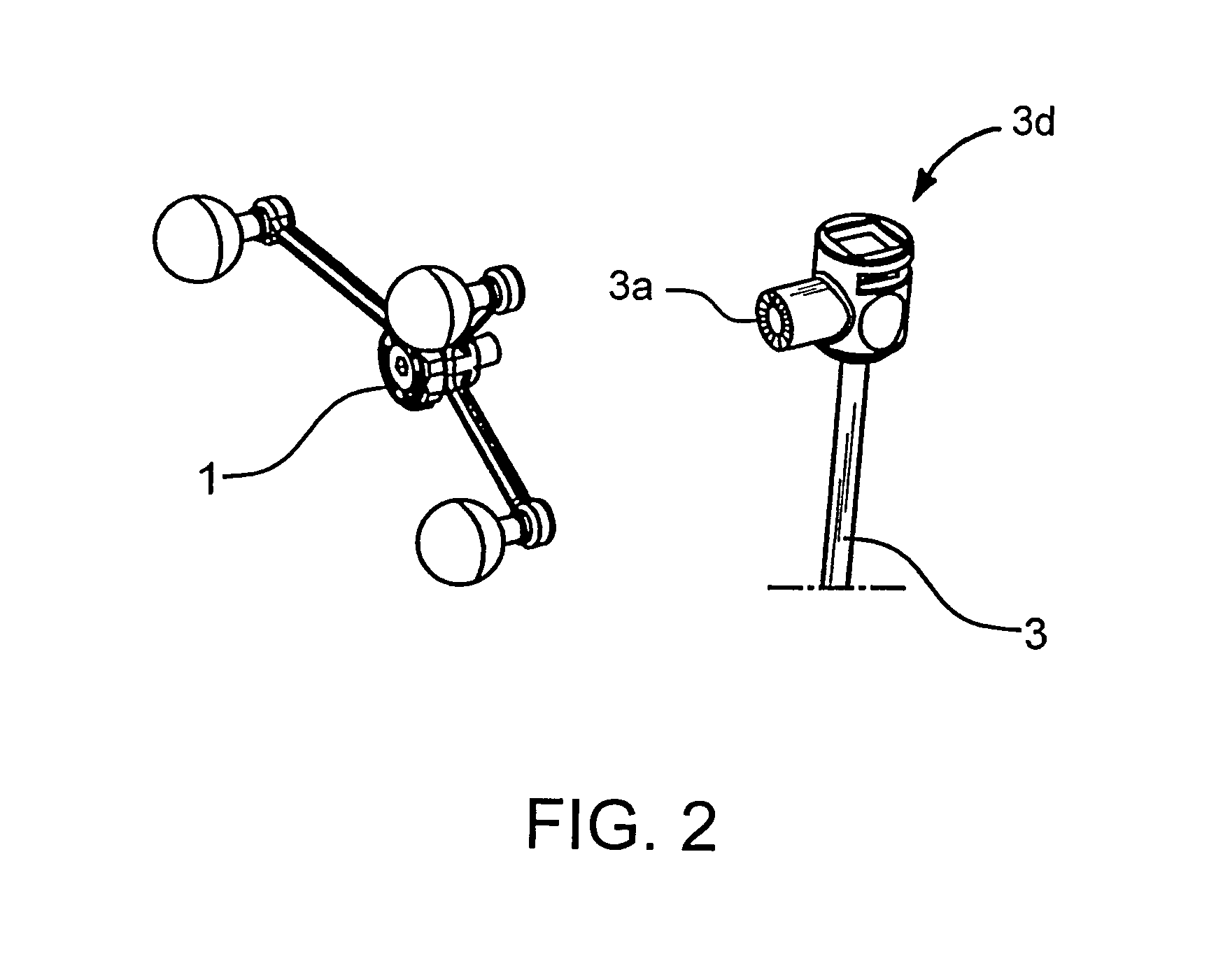
[0031]FIG. 1 shows the elements of an exemplary guide tube fixation device in accordance with the invention. A fixation clamp 6 includes two clamp jaws 6a and 6b and a centrical threaded rod to tension the jaws 6a and 6b. The clamp 6 also includes a sphere 7 to be used as a ball joint sphere, on which a ball joint unit 2 is attached so as to enable adjustment of a distal tip 3b of the guide tube 3 and, thus, of a spinal needle 5 guided by the guide tube 3. The guide tube 3 can be inserted through a hole of the ball joint unit 2 and can include a connecting element 3a for attaching a reference star 1 (e.g., the connecting element 3a can include an instrument adapter star having for example a StarLink interface). A spinal needle 5 can be guided through the guide tube 3 until the distal tip 5a of the spinal needle 5 exits the distal or frontal end 3b of the guide tube 3. A position of the spinal needle 5 can be fixed to the guide tube 3 by means of a fixation flap 4.

[0032]FIG. 2 shows ...


PUM


Abstract

An apparatus and method for positioning a guide tube fixation device at a spinal structure of a patient are provided. The method includes attaching an attachment element to the spinal structure, attaching a guide tube to the attachment element, wherein said guide tube is calibrated prior to attachment, and navigating a part of the guide tube to a predetermined location relative to a target region of the patient. The apparatus includes an attachment device for attaching to the spinal structure, a joint attached to the attachment device, and a guide tube holding device attached to the joint and operable to hold and / or guide a guide tube, said guide tube configured to guide a cannula, needle and / or fluid to a desired site or location.

Description

RELATED APPLICATION DATA[0001]This application claims priority of U.S. Provisional Application No. 60 / 910,236 filed on Apr. 5, 2007, which is incorporated herein by reference in its entirety.FIELD OF THE INVENTION[0002]The present invention relates to an application guide and, more particularly, to a guide tube fixation device for fixing a guide tube in the area of the spinal cord, the use of such a guide tube fixation device for guiding a needle or cannula, and a method for positioning such a guide tube fixation device at a structure, such as a vertebra.BACKGROUND OF THE INVENTION[0003]Typical vertebral column surgical procedures include vertebral fusion, insertion of implants such as pedicle screws, discography, percutaneous disectomy, or the like. These procedures typically require a large invasive operation that exposes the patient to a high risk of infection, excessive trauma, blood or fluid loss, post operative pain, scaring, and lengthy recovery time.[0004]Some difficulties r...

Claims


Application Information

Patent Timeline
Patent Type & Authority Patents(United States)
IPC IPC(8): A61B17/58A61B17/60A61F2/00A61B19/00A61B17/00A61B17/34
CPCA61B19/26A61B19/201A61B19/5244A61B19/56A61B2017/00261A61B2017/3407A61B2019/5483A61B2090/3983A61B34/20A61B34/25A61B90/50A61B90/11
Inventor BRUNDOBLER, MATTHIASLECHNER, CHRISTIAN
Owner BRAINLAB
Why Eureka
Try Eureka