Motor mounted switch

a technology of motors and switches, applied in the direction of coupling device connections, contacts, dynamo-electric machines, etc., can solve the problems of preventing shorting between the windings and the stator, reducing the reducing the service life of the rotor, so as to prevent shorting and add longevity to the rotor

Inactive Publication Date: 2002-04-23
TATEISHI ART
View PDF13 Cites 28 Cited by
  • Summary
  • Abstract
  • Description
  • Claims
  • Application Information

AI Technical Summary

Benefits of technology

According to another aspect of the invention, the stator of the motor construction includes a resin bobbin which is accurately injection molded to the main metallic body of the stator. This bobbin receives and isolate the magnetic flux wires from the metal body of the stator eliminating the separate dipping processes and the like which have been used in the past on a somewhat ineffective basis to prevent shorting between the windings and the stator.
The injection molding of the bobbin also eliminates the old requirement of riveting the entire stator parts together. This is not necessary in accordance with the present invention where the stator and bobbin are secured by the molding process.
According to still a further aspect of the present invention, the motor construction includes an extremely efficient lubricating bearing assembly adding longevity to rotor life.
According to yet a further preferred embodiment of the present invention a substantial part of the overall appliance including the bearing housing, the motor housing and the switch housing and switch body are all made from plastic in a single injection molding operation. This plastic is one with suitable electrical and mechanical properties to comply with OSHA standards and to pass UL and CSA testing. Furthermore, most of these components are ready to assemble with one another by automatic interlock fittings eliminating the requirement for separate mechanical fasteners throughout most of the overall appliance construction.

Problems solved by technology

Conventional manufacturing of electrical appliance motors is both time consuming and relatively expensive.
For example, according to known methods of making a stator of a multiple pole motor there are difficulties in insulating the flux wires from the metallic body of the stator.
However, even after the above steps are taken, there is no guarantee that there may still not be areas of electrical conductivity between the stator and the flux wires which produce electrical shorting of the motor which will show up in the High Pot Test.
In addition to not necessarily being completely efficient, the above steps are also very labour intensive adding significantly to the cost of the motor.
Again, in a traditional electrical appliance motor, it is very difficult to maintain lubrication of the rotor in the motor.
Traditional bearings may not be effective and may result in overheating of the motor.
A further difficulty encountered in the manufacturing of a standard electrical appliance motor relates to the actual wiring of the motor.
Again, this is very labour intensive and substantially slows down the assembly time for the overall motor.
In addition, it necessitates the use of relatively costly leads and additionally necessitates the use of expensive multipole switches that must then be mounted to a separate location on the appliance.
As a further drawback, electrical appliances such as electrically operated fans traditionally use mostly metal components which are all manufactured separately from one another and which then are typically secured by mechanical fasteners such as screws further adding to the cost of the appliance from both a material and a labour standpoint.

Method used


Image

  • Motor mounted switch
  • Motor mounted switch
  • Motor mounted switch

Examples


Embodiment Construction

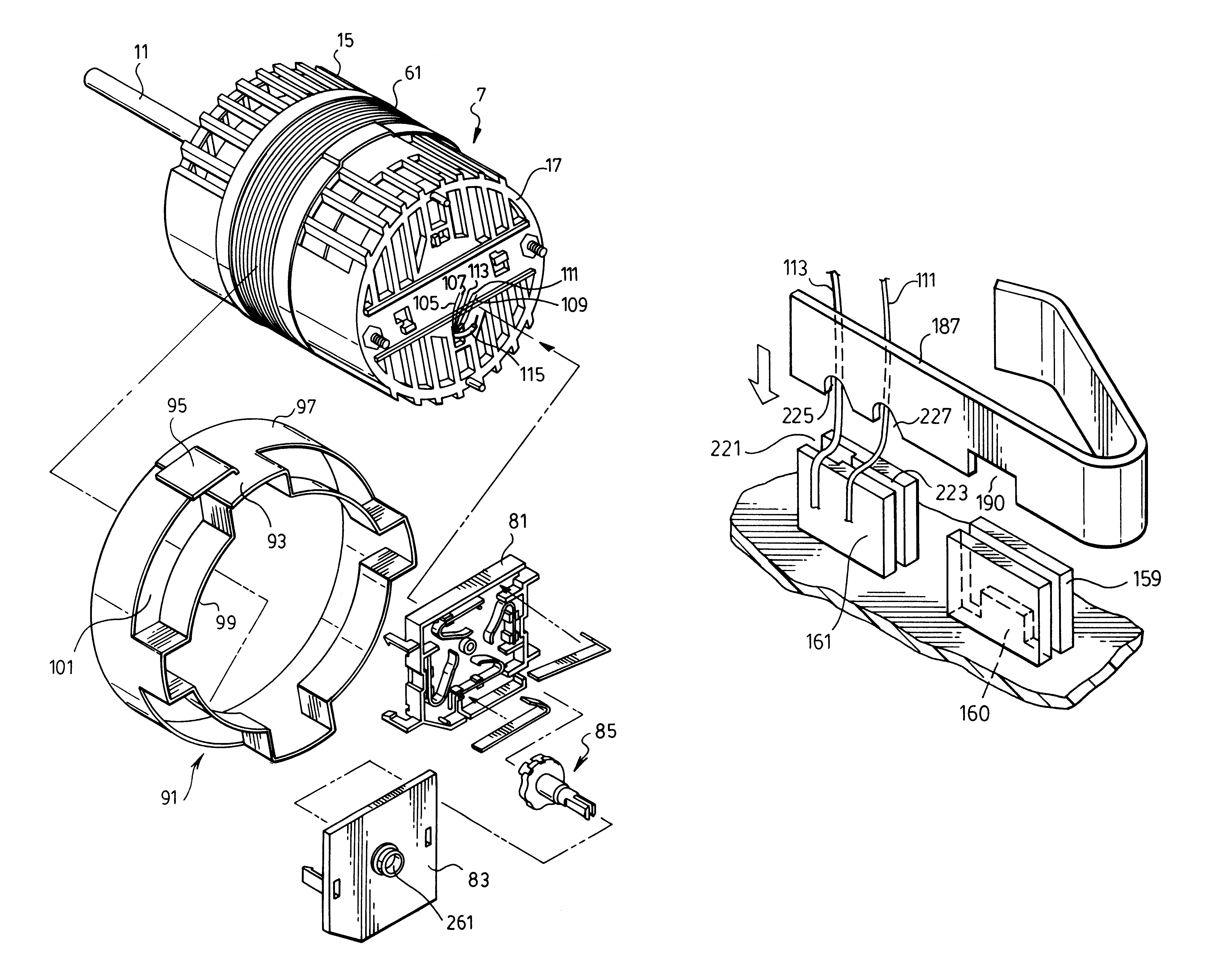
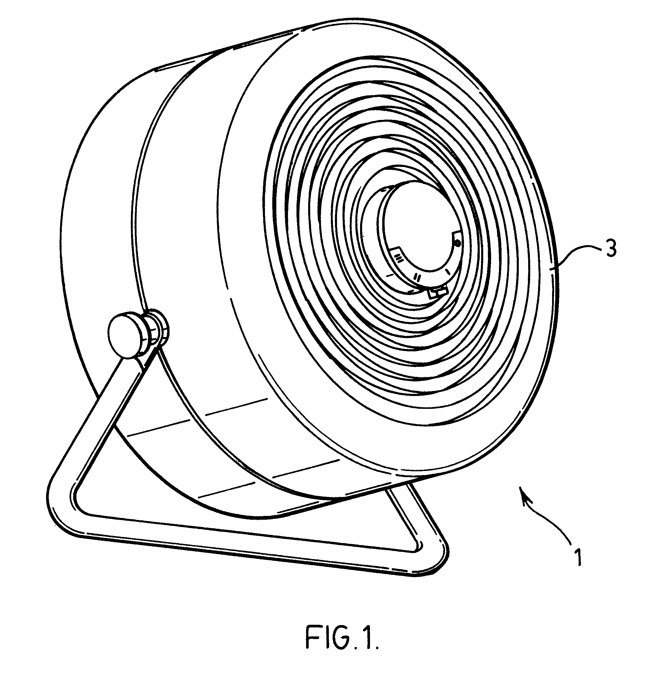
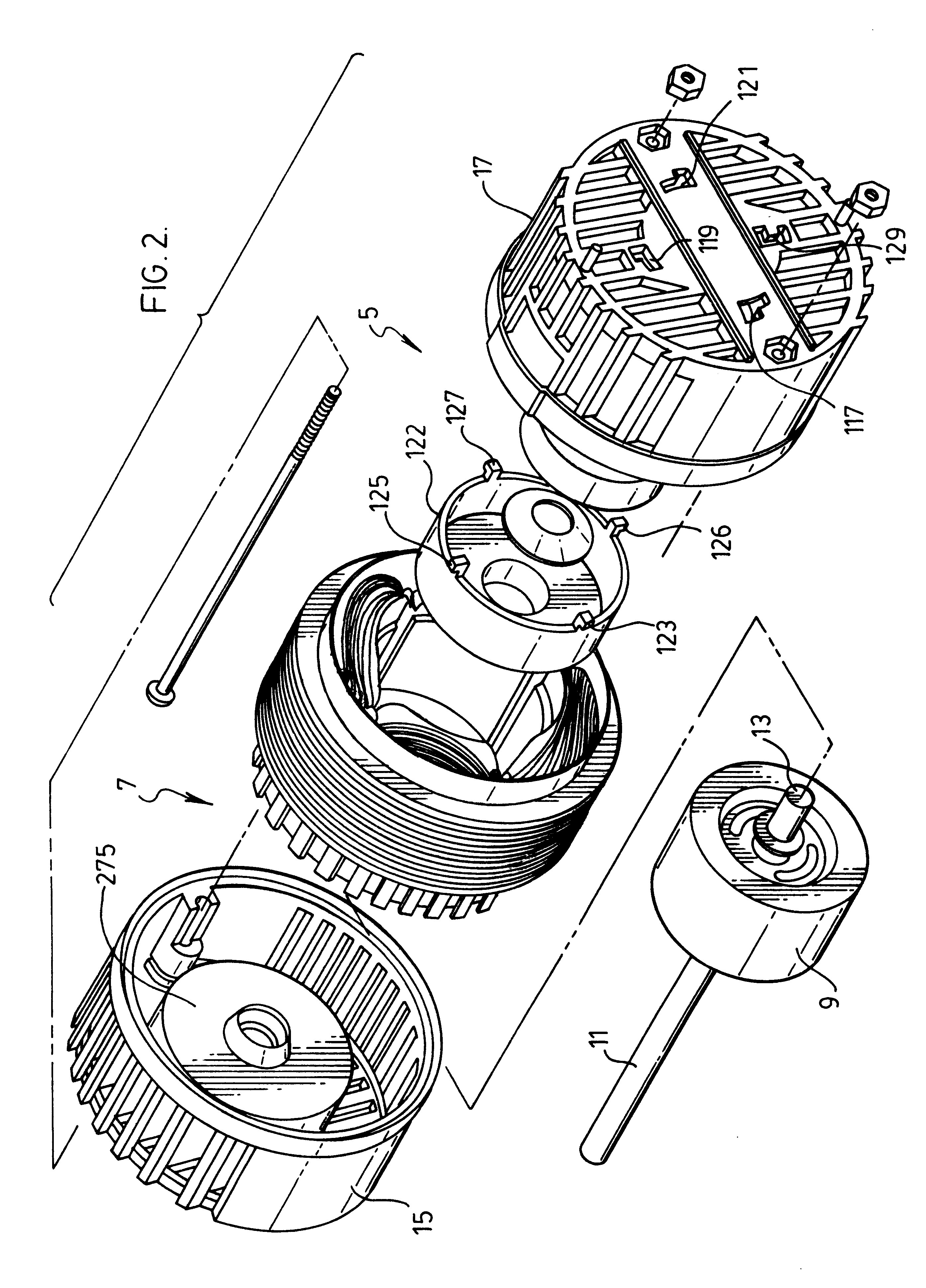
FIG. 1 show an electrical appliance and specifically a multi-speed electric fan generally indicated at 1. This fan includes a main fan housing 3 containing internal components including a motor construction generally indicated at 5 in FIG. 2 of the drawings.

The motor construction is built around a stator generally indicated at 7 and a rotor 9 which rotates within stator 7. Rotor 9 includes shaft portions 11 and 13 which are trapped within and lubricated by the housing and lubricated at bearing regions for the motor which is formed by main motor housing sections 15 and 17.

FIG. 4 of the drawings shows the main metallic body portion 19 of stator 7. This metallic body portion is formed by a plurality of metallic layers 21 laminated to one another.

According to a preferred feature of the invention, the stator which, in this case, is used to form a four pole motor is completed by forming a bobbin have four separate winding regions 23, 25, 27 and 29 from resin material injection molded dire...


PUM


Abstract

An electrical appliance which operates at multiple speeds includes a motor construction having a stator and a rotor which rotates within the stator. The stator includes a plurality of magnetic flux inducing wires coiled on different poles of the stator. The stator and the rotor are contained within a motor housing with the appliance further including a switch housing mounted directly to the motor housing. The flux inducing wires have wire ends which extend out of the motor housing and into the switch housing which includes receptors to receive the ends of the flux inducing wires and which also receive electrical contact members which secure and electrically connect with the ends of the flux inducing wires within the receptors of the switch housing.

Description

The present invention relates very generally to a motor construction for use in an electrical appliance which operates at different motor speeds.Conventional manufacturing of electrical appliance motors is both time consuming and relatively expensive. For example, according to known methods of making a stator of a multiple pole motor there are difficulties in insulating the flux wires from the metallic body of the stator. Typically, the entire stator must be coated or treated with material such as fish paper to prevent the windings of the coil from contacting the stator body. The stator must then be capable of passing what is known in the industry as a High Pot Test. However, even after the above steps are taken, there is no guarantee that there may still not be areas of electrical conductivity between the stator and the flux wires which produce electrical shorting of the motor which will show up in the High Pot Test.In addition to not necessarily being completely efficient, the abo...

Claims


Application Information

Patent Timeline
Patent Type & Authority Patents(United States)
IPC IPC(8): H01H11/06H01H11/04H02K3/52H02K5/167H02K3/46H02K5/22H02K15/02H01H19/00H01H19/54H02K11/00H01H1/00H01H1/58
CPCH01H11/06H01H19/54H02K15/022H02K3/522H02K5/1672H02K5/225H02K11/0063H01H1/5844H01H1/585H01H2011/062H02K11/28
Inventor TATEISHI, ART
Owner TATEISHI ART
Why Eureka
Try Eureka