Blowing desulfurization fluidization device

A fluidization device and desulfurization agent technology, which is applied in the field of metallurgy, can solve the problems of unstable desulfurization agent feeding speed, uneven fluidization of desulfurization agent, serious splashing, etc.

Inactive Publication Date: 2015-03-18
PANGANG GROUP RESEARCH INSTITUTE CO LTD +2
View PDF5 Cites 0 Cited by
  • Summary
  • Abstract
  • Description
  • Claims
  • Application Information

AI Technical Summary

Problems solved by technology

The existing injection desulfurization fluidization device has uneven fluidization effect on the desulfurization agent, resulting in unstable feeding speed of the desulfu

Method used


Image

  • Blowing desulfurization fluidization device
  • Blowing desulfurization fluidization device
  • Blowing desulfurization fluidization device

Examples


Embodiment Construction

[0032] Specific embodiments of the present invention will be described in detail below in conjunction with the accompanying drawings. It should be understood that the specific embodiments described here are only used to illustrate and explain the present invention, and are not intended to limit the present invention.

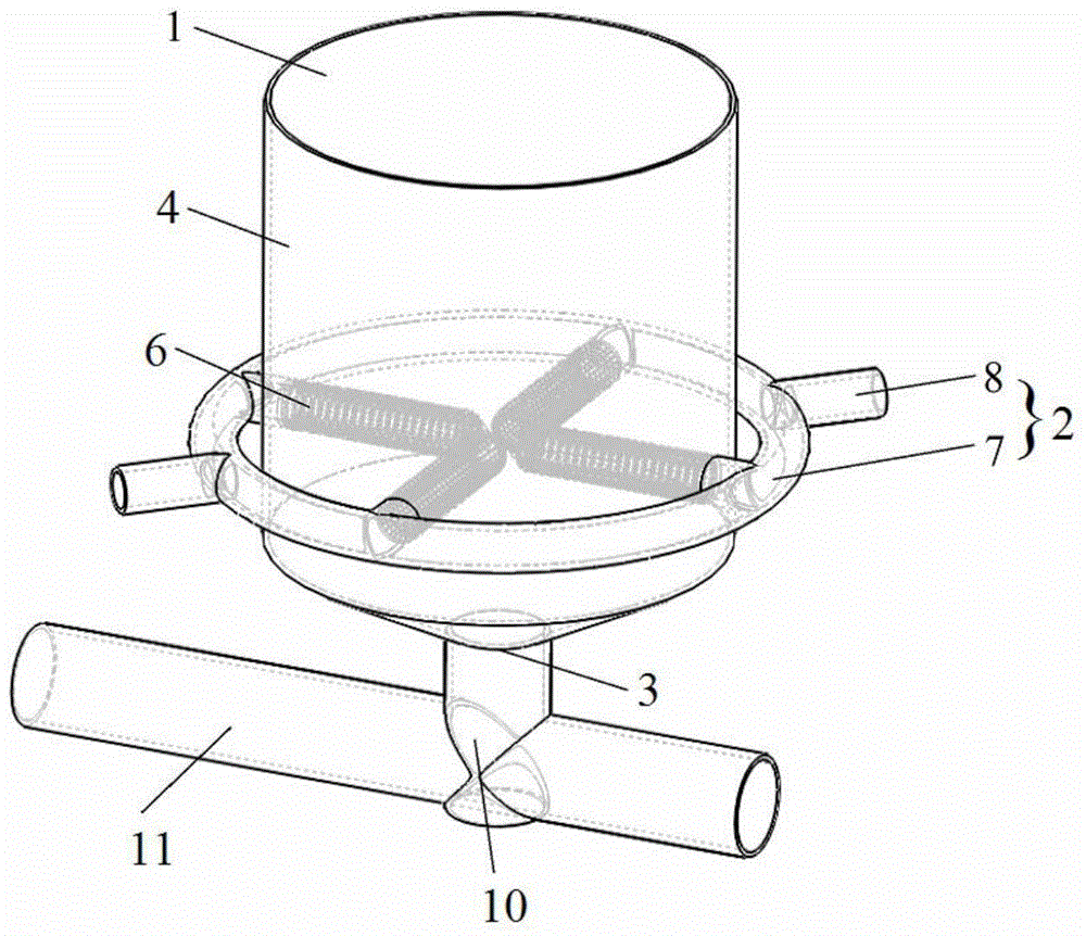
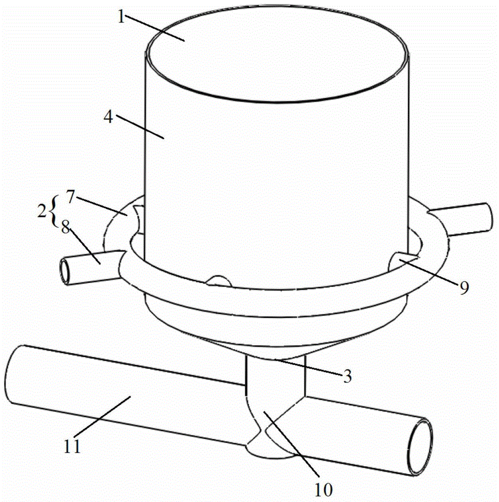
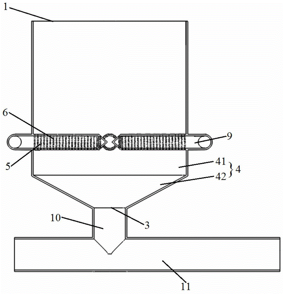
[0033] Such as figure 1 with figure 2 As shown, the specific embodiment of the present invention provides an injection desulfurization fluidization device, wherein the injection desulfurization fluidization device includes a housing 4 with a desulfurization agent inlet 1 and a desulfurization agent outlet 3 arranged along the height direction , an air supply channel 2 and an air distribution pipe 6 densely covered with a plurality of air outlet holes 5. The housing 4 is formed as a fluidization chamber, and the air distribution pipe 6 is arranged in the fluidization chamber and located in the desulfurization chamber. Between the desulfurizer inlet 1 and the d...


PUM


Abstract

The invention discloses a blowing desulfurization fluidization device. The blowing desulfurization fluidization device comprises a housing (4), a gas supply passage (2) and an air distribution pipe (6), wherein a desulfurizer inlet (1) and a desulfurizer outlet (3) are formed in the housing (4) along the height direction of the housing, a plurality of air outlet holes (5) are densely distributed in the air distribution pipe (6), a fluidization chamber is formed inside the housing (4), the air distribution pipe (6) is arranged inside the fluidization chamber and located between the desulfurizer inlet (1) and the desulfurizer outlet (3), the gas supply passage (2) is communicated with the air distribution pipe (6) and the gas supplied by virtue of the gas supply passage (2) is blown into the fluidization chamber by virtue of the plurality of air outlet holes (5) formed in the air distribution pipe (6). By the blowing desulfurization fluidization device, the desulfurizer can be uniformly fluidized during the charging of the desulfurizer, good fluidization effect is achieved so that the charging speed of the desulfurizer is stable, the blowing process time is shortened, the spattering is reduced and the amount of iron loss is decreased.

Description

technical field [0001] The invention relates to the field of metallurgy, in particular to an injection desulfurization fluidization device. Background technique [0002] Pneumatic conveying is a method of transporting solid materials in the pipeline along the airflow direction by using airflow with a certain speed and pressure. Pneumatic conveying has the advantages of safety, low cost, easy automation, environmental protection, simple structure, convenient operation, and flexible conveying direction. At the same time, during the transportation process, it can also perform physical operations such as heating, cooling, drying and airflow classification, or some chemical operations, and is widely used in various industries such as electric power, chemical industry, building materials, steel, and food. [0003] Powder spraying metallurgy is a metallurgical technology that makes metallurgical solid materials into powder or fine particles, uses gas as a carrier for pneumatic conv...

Claims


Application Information

Patent Timeline
IPC IPC(8): C21C7/064
Inventor 陈永梁新腾曾建华韩光华李扬洲杨森祥黄正华张家利戈文荪陈炼龚洪君喻林
Owner PANGANG GROUP RESEARCH INSTITUTE CO LTD
Why Eureka
Try Eureka