
An assembly line loading and unloading structure

A technology of assembly line and material transportation, applied in the direction of conveyor objects, transportation and packaging, conveyors, etc.

Active Publication Date: 2021-04-23
嵊州市法克机械有限公司
View PDF15 Cites 0 Cited by
  • Summary
  • Abstract
  • Description
  • Claims
  • Application Information

AI Technical Summary

Problems solved by technology

[0004] The object of the present invention is to provide an assembly line loading and unloading structure to at least solve the problems of loading and unloading speed and application cost in the prior art

Method used

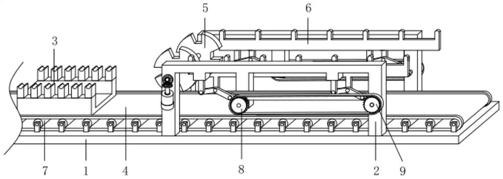
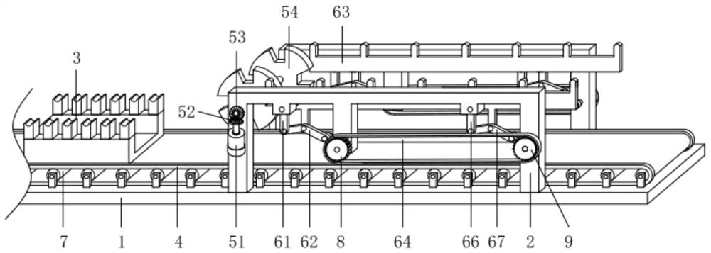
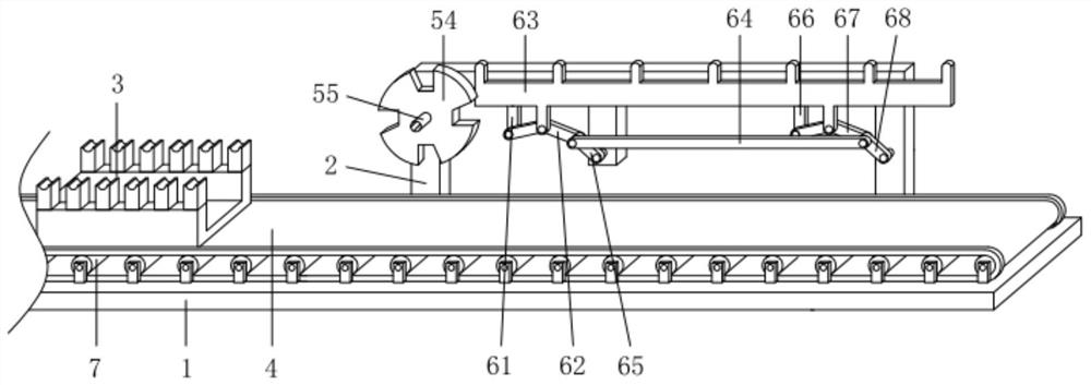

Image

  • An assembly line loading and unloading structure
  • An assembly line loading and unloading structure
  • An assembly line loading and unloading structure

Examples


Embodiment Construction

[0018] The following will clearly and completely describe the technical solutions in the embodiments of the present invention with reference to the accompanying drawings in the embodiments of the present invention. Obviously, the described embodiments are only some, not all, embodiments of the present invention. Based on the embodiments of the present invention, all other embodiments obtained by persons of ordinary skill in the art without making creative efforts belong to the protection scope of the present invention.

[0019] see Figure 1-3 , the present invention provides a technical solution: an assembly line loading and unloading structure, including a base 1, and also includes a bracket 2, a material tray 3, a conveyor belt 4, a retrieving mechanism 5, a material conveying mechanism 6, a rotating roller 7, and a first gear 8 and the second gear 9, there are two brackets 2, and the two brackets 2 are respectively arranged on the front and rear sides of the upper surface ...


PUM


Abstract

The invention discloses a material loading and unloading structure on an assembly line, which includes a base and a bracket. The brackets are two. The left side of the inner wall is provided with connecting blocks and rollers along the up and down directions. Several of the rollers are arranged on the upper surface of the base in sequence along the left and right directions, and the front and rear ends of the rollers are connected with the upper surface connecting seats of the base through pin shafts. , the conveyor belt, the conveyor belt is arranged on the upper and lower sides of the outer wall of the rotating roller, the material tray, the material tray is arranged on the upper surface of the conveyor belt, the first gear, and there are two first gears. The assembly line loading and unloading structure can stably take out the workpieces, and can feed the workpieces to the processing equipment one by one, realizing mechanical loading and unloading and stacking instead of manual loading and unloading, saving labor and ensuring the speed of feeding. It is stable, reduces the production cost, and is conducive to popularization.

Description

technical field [0001] The invention relates to the technical field of machining, in particular to an assembly line loading and unloading structure. Background technique [0002] In the manufacturing process, the reasonable allocation of labor efficiency is one of the key points of production-oriented enterprises currently operating on the assembly line. The assembly line involves the loading and unloading of products, and the speed of loading and unloading determines the efficiency and efficiency of the assembly line operation. The cost of the workpiece, the current assembly line generally uses manual or mechanical loading and unloading; [0003] Shaft workpieces generally require workers to manually load, unload, and stack materials before and after processing, and need to wait between processing intervals. This is not only time-consuming and laborious, but also cannot guarantee production speed. Robots are generally used for processing large workpieces, and high precision...

Claims


Application Information

Patent Timeline
Patent Type & Authority Patents(China)
IPC IPC(8): B65G23/04B65G23/22B65G15/30B65G47/84B65G47/74
CPCB65G15/30B65G23/04B65G23/22B65G47/74B65G47/846
Inventor 竺叶飞
Owner 嵊州市法克机械有限公司
Learn More