
System and method for reducing friction in engines

A technology for internal combustion engines and vehicle systems, applied in the direction of engine components, machines/engines, charging systems, etc., can solve problems such as reducing fuel economy, increasing engine component resistance, increasing engine load, etc.

Inactive Publication Date: 2015-03-18
FORD GLOBAL TECH LLC
View PDF4 Cites 0 Cited by
  • Summary
  • Abstract
  • Description
  • Claims
  • Application Information

AI Technical Summary

Problems solved by technology

Entrained oil droplets further increase drag on engine components, increasing engine load and reducing fuel economy

Method used


Image

  • System and method for reducing friction in engines
  • System and method for reducing friction in engines
  • System and method for reducing friction in engines

Examples


Embodiment Construction

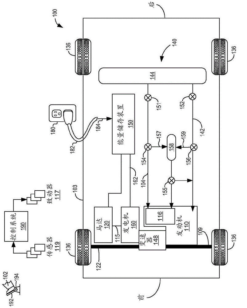
[0036] In the vehicle's propulsion system, the power loss caused by air resistance is proportional to the density of the gas or liquid in which the components rotate. Therefore, the power loss caused by air resistance can be reduced by reducing the density of the gas surrounding the transmission, electric motor, or generator in the box.

[0037] During the rotation, the friction between the components generates a lot of heat. To prevent the engine from overheating, this heat can be removed from the components and transferred to other places. This can be achieved by the cooling system during operation or the movement of the vehicle when the components are in contact with the cooler gas, which absorbs heat from the system and transfers the heat to the atmosphere or the cabin. Therefore, although the power loss is greatly reduced in the airless vacuum or low-pressure box, the cooling effect will be reduced or disappeared, resulting in engine degradation. Therefore, when determinin...


PUM


Abstract

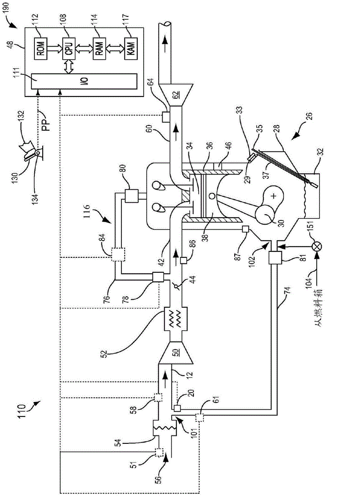
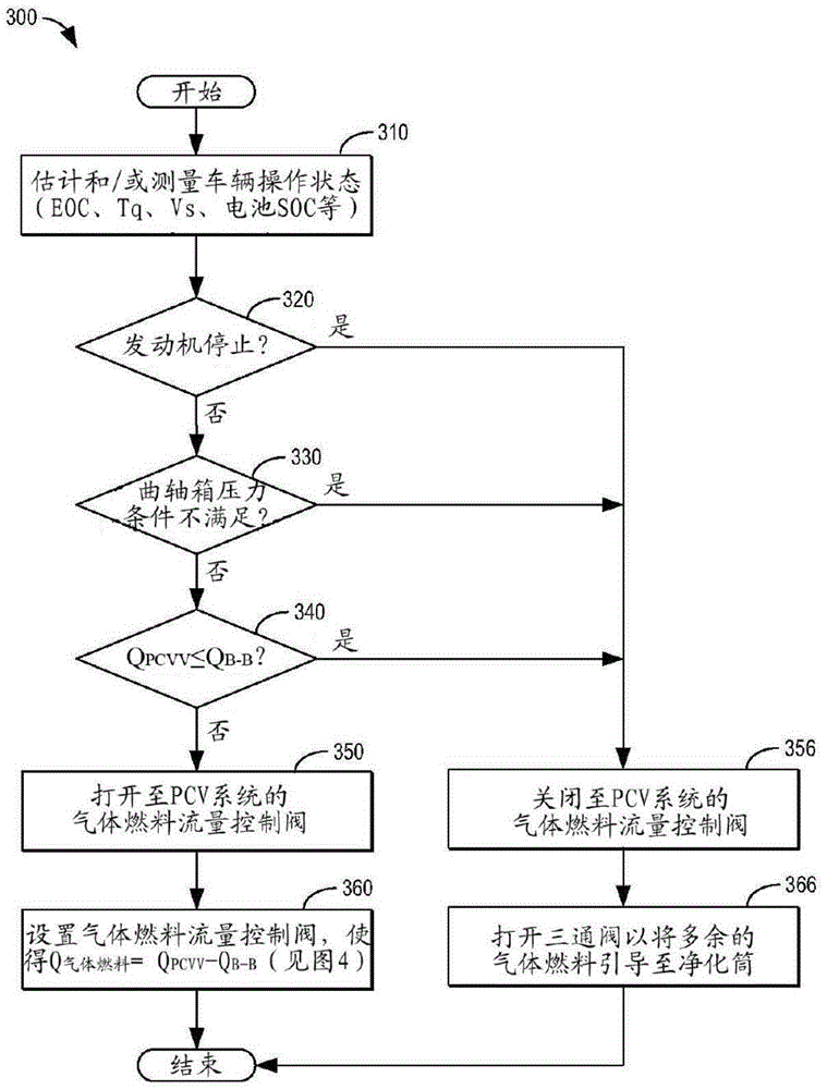
A vehicle system comprises an internal combustion engine including a PCV system fluidly coupled to a gaseous fuel source via a flow control valve. The gaseous fuel source may be fluidly coupled to an air inflow line of the PCV system, and the flow control valve may be configured to control a flow of gaseous fuel into the PCV system.

Description

Background technique [0001] Internal combustion engines rely on high-speed rotating machinery and gears that rotate in the air. The drag and friction from the air around the moving parts of the vehicle propulsion system cause fuel efficiency losses. A device such as an oil baffle is usually used to reduce the entrainment of oil droplets in the oil pan / sump into the air around the moving parts of the engine, thereby alleviating the aerodynamic friction of the rotating and reciprocating parts in the engine crankcase. The entrained oil droplets further increase the resistance acting on the engine components, thereby increasing the load on the engine and reducing fuel economy. In addition, in the power generation industry, high-speed electrical machinery is placed in hydrogen (which has a lower viscosity than air) to reduce friction from the surrounding air. [0002] The inventor has realized some of the problems with the above method. That is, although the oil baffle and similar d...

Claims


Application Information

Patent Timeline
Patent Type & Authority Applications(China)
IPC IPC(8): F01M13/00
CPCF02M21/0218F01M13/02F01M13/028F01M13/022
Inventor 大卫·卡尔·比德纳
Owner FORD GLOBAL TECH LLC
Learn More