
Apparatus and method for measuring parameters of transient plasmas in high-speed impact

An ultra-high-speed impact and plasma technology, applied in the aerospace field, can solve the problems of difficult to accurately design microwave and laser transmission paths, difficult to meet the plasma parameter measurement, low plasma energy, etc., to achieve perfect shielding design, good time The effect of distinguishing characteristics and accurate measurement results

Inactive Publication Date: 2015-03-18
NAT SPACE SCI CENT CAS
View PDF5 Cites 4 Cited by
  • Summary
  • Abstract
  • Description
  • Claims
  • Application Information

AI Technical Summary

Problems solved by technology

Due to the low energy (1-10eV) of the plasma formed by the ultra-high-speed impact of space debris, the plasma will be seriously lost during the diffusion to the sensor, resulting in low collection efficiency
[0006] 2. Insufficiency of the non-contact method for measuring ultra-high-speed impinging transient plasma parameters
The location of the plasma generated by the ultra-high-speed impact of space debris is random, so it is difficult to accurately design the transmission paths of microwaves and lasers
[0008] In summary, traditional plasma diagnostic methods are difficult to measure plasma parameters in space debris hypervelocity impacts.

Method used


Image

  • Apparatus and method for measuring parameters of transient plasmas in high-speed impact
  • Apparatus and method for measuring parameters of transient plasmas in high-speed impact
  • Apparatus and method for measuring parameters of transient plasmas in high-speed impact

Examples


Embodiment Construction

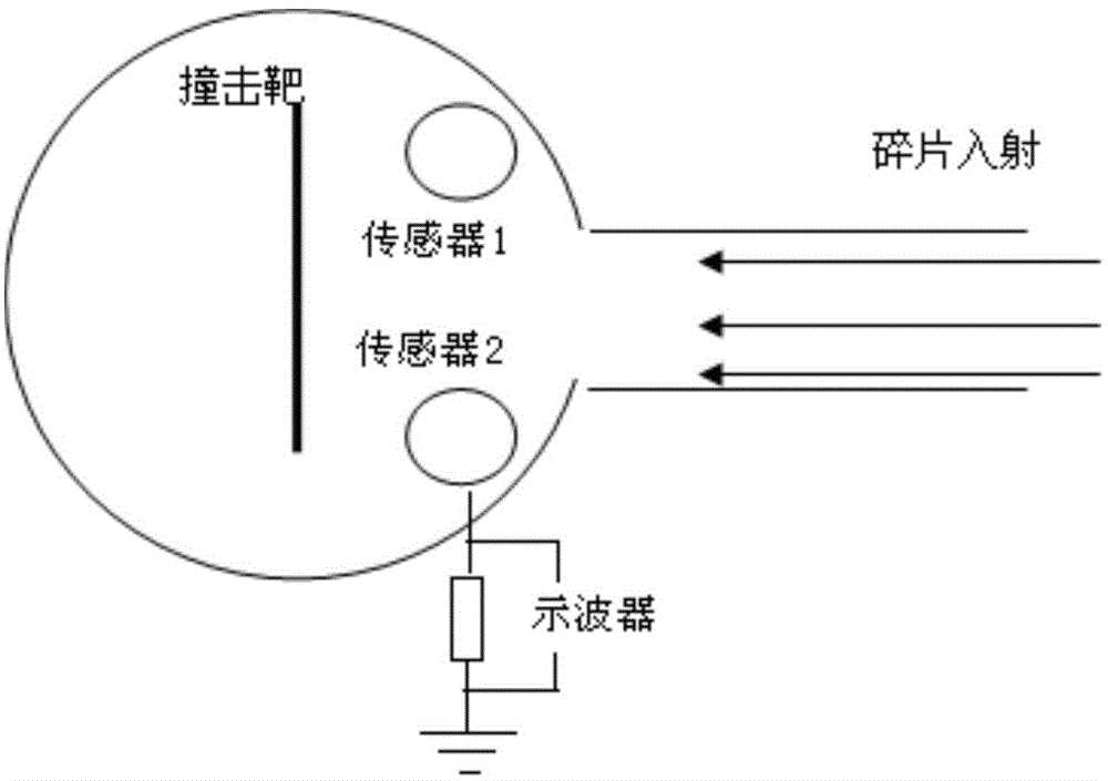
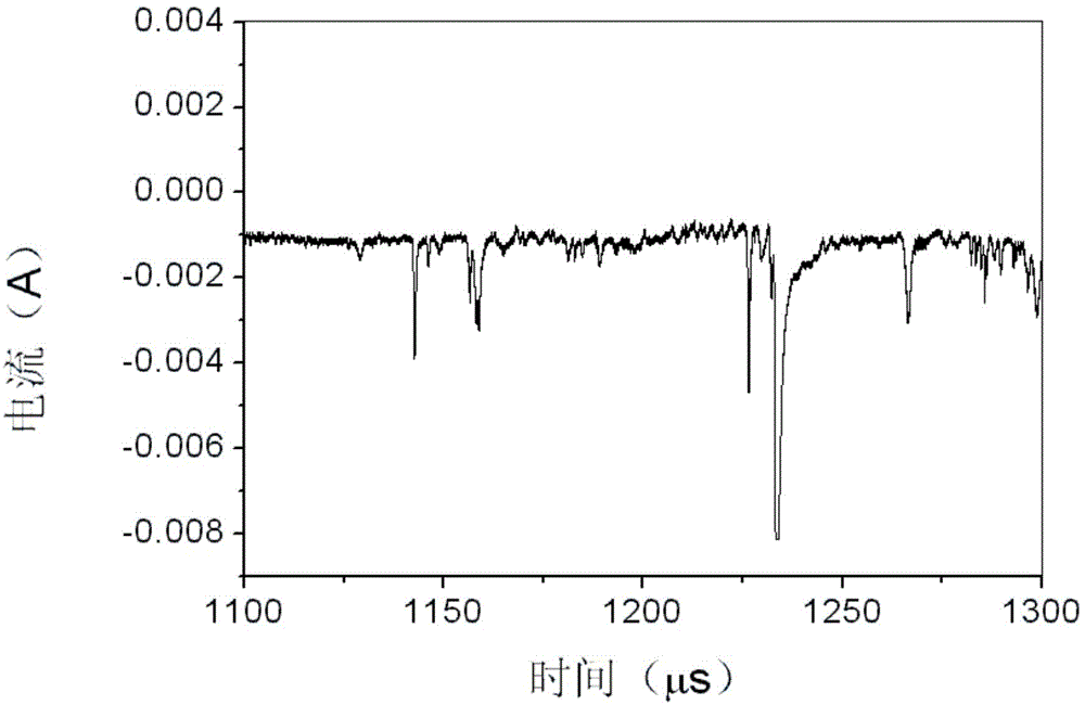
[0040] The present invention will be further described now in conjunction with accompanying drawing.

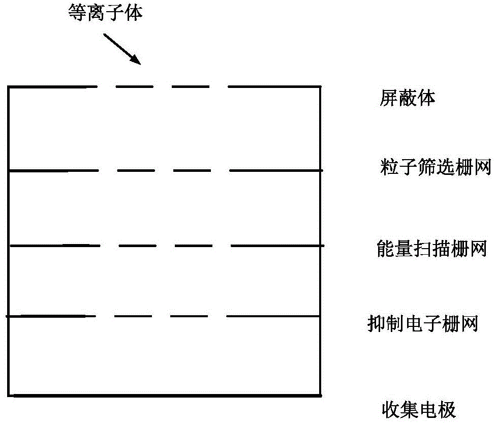
[0041] The device of the present invention for measuring transient plasma parameters in space debris ultra-high-speed impacts includes a multilayer grid sensor, a power supply and an oscilloscope; wherein, the power supply provides electrical energy for the multilayer grid sensor and the oscilloscope, and the The multi-layer grid sensor uses the charged grid to analyze the plasma energy formed by the impact of space debris, thereby obtaining parameters including plasma density, energy, and diffusion speed; the obtained results are displayed on the oscilloscope.

[0042] exist figure 1 The structure of the multi-layer grid sensor is further described in . As shown in the figure, the sensor includes in order from top to bottom: a shield, a particle screening grid, an energy scanning grid, an electron suppression grid, and a collecting electrode; the shield is used to shield the ...


PUM


Abstract

The invention relates to an apparatus and method for measuring the parameters of transient plasmas in high-speed impact. The apparatus includes a multilayer grid sensor, a power source and an oscilloscope; according to the multilayer grid sensor, the energy of plasmas in space debris impact can be analyzed by using electrified grids, so that parameters including the density, energy and diffusion speed of the plasmas can be obtained; the obtained results are displayed on the oscilloscope; the multilayer grid sensor includes a shielding body, a particle screening grid, an energy scanning grid, a suppression electron grid and a collection electrode which are distributed sequentially from top to bottom; the shielding body is used for shielding an internal electric field, so that voltage applied to each layer of grid can be prevented from affecting an external plasma environment; the particle screening grid is used for distinguishing positive and negative particles; the energy scanning grid obtains energy information of the particles by applying scanning bias voltage; the suppression electron grid not only can prevent the emission of secondary electrons and photoelectrons on the collection electrode, but also can prevent interference on front-end electronics; and the collection electrode is used for collecting the plasmas.

Description

technical field [0001] The invention relates to the aerospace field, in particular to a device and method for measuring transient plasma parameters in ultra-high-speed impacts. Background technique [0002] The impact of space debris on spacecraft materials at ultra-high speed can locally generate a transient plasma environment, which threatens the safe and reliable operation of spacecraft in orbit. The typical speed range of space debris is 1-15km / s. When space debris hits the surface of spacecraft materials at ultra-high speed, part of the kinetic energy will be converted into gasification energy and ionization energy. The ionization of debris and target materials will form a local dense transient plasma cloud. There are two main mechanisms by which the transient plasma cloud formed by the impact of space debris affects the spacecraft. One is that the dense plasma formed by the impact covers the charged area of ​​the spacecraft, causing electrostatic discharge in this are...

Claims


Application Information

Patent Timeline
IPC IPC(8): G01D21/02
Inventor 蔡明辉李宏伟吴逢时杨涛张振龙汪金龙韩建伟
Owner NAT SPACE SCI CENT CAS
Learn More