Method and x-ray system for generating a phase contrast image

A phase contrast, X-ray technology, applied in the field of X-ray systems

Inactive Publication Date: 2015-03-18
SIEMENS AG
View PDF6 Cites 4 Cited by
  • Summary
  • Abstract
  • Description
  • Claims
  • Application Information

AI Technical Summary

Problems solved by technology

[0005] Therefore, the technical problem to be solved by the present invention is to find a method for graphically reconstructing an examination object based on the phase shift value of the transmitted electromagnetic radiation, which method uses the dose which is regarded as acceptable for a living examination object Image results with the lowest possible noise in the burdened inspection range

Method used


Image

  • Method and x-ray system for generating a phase contrast image
  • Method and x-ray system for generating a phase contrast image
  • Method and x-ray system for generating a phase contrast image

Examples


Embodiment Construction

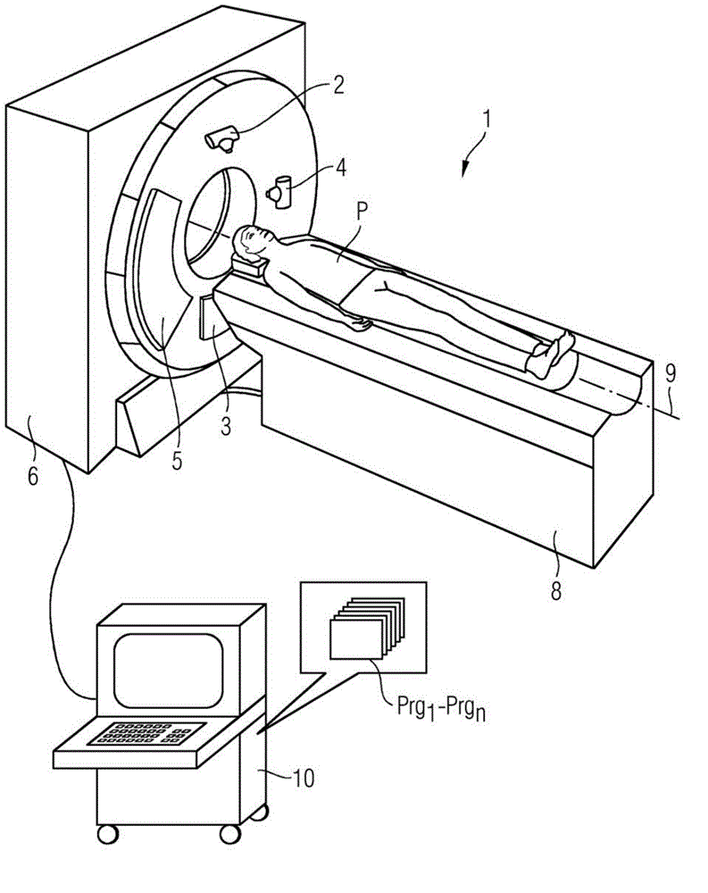
[0049] figure 1 Shown is a dual-energy CT system 1 with a gantry housing 6, in which two radiator-detector systems 2, 3 and 4, 5 are located on a gantry not shown in detail, which respectively It has an X-ray tube 2 or 4 and an opposite detector 3 or 5 . With the two emitter-detector systems CT recordings with different X-ray energy spectra are produced from a patient P through which the patient is moved for examination by means of a patient table 8 movable along the system axis 9 The measurement area between systems. System control is performed by a computer system 10 with a corresponding program.

[0050] According to the invention, in the memory of the computer system 10 there is also the program Prg 1 -Prg n , which executes the method according to the invention in operation by determining the local electron density in the patient from previously determined absorption recordings, for example by elementary material decomposition or by determining the absorption fraction...


PUM


Abstract

A method and an X-ray system are disclosed for generating a phase contrast image of an examination object. In an embodiment, the distribution of an electron density in the examination object is determined by defining energy-dependent attenuation values for X-radiation with at least two different X-ray energy spectra, phase-shift values are obtained from the previously determined electron density distribution, and a phase contrast image is generated from the calculated phase-shift values.

Description

technical field [0001] The invention relates to a method for producing a phase-contrast representation of an examination object and an x-ray system for carrying out the method. Background technique [0002] The optical properties of the material with respect to X-rays are characterized by the so-called complex refractive index. Although conventional X-ray imaging with a fixed spectrum directly measures the imaginary part of the complex refractive index, it does not have access to the real part describing the phase shift of the X-ray radiation. There is an idea that phase information can be used in medical diagnosis for better separation of soft tissues. [0003] Various methods have been developed in the past which are able to show the influence of the examination object on the phase of electromagnetic waves (in particular X-rays of a certain energy) penetrating the examination object. Such a display is usually referred to as a phase-contrast recording or a tomographic pha...

Claims


Application Information

Patent Timeline
Patent Type & Authority Applications(China)
IPC IPC(8): A61B6/00G01N23/00
CPCA61B6/5205A61B6/5217G01N2223/419A61B6/482A61B6/032G01N23/046A61B6/484A61B6/4007G16H50/30
Inventor T.弗洛尔R.劳帕克
Owner SIEMENS AG
Why Eureka
Try Eureka