Centrifugal compressor

A centrifugal compressor and housing technology, applied in mechanical equipment, engine components, engine manufacturing, etc., can solve problems such as small flow range, and achieve the effects of expanding operating range, reducing flow resistance, and improving surge margin

Active Publication Date: 2015-03-18
MITSUBISHI HEAVY IND LTD
View PDF7 Cites 20 Cited by
  • Summary
  • Abstract
  • Description
  • Claims
  • Application Information

AI Technical Summary

Problems solved by technology

[0004] However, in an ordinary compressor type centrifugal compressor in which the direct intake air is sucked by the impeller, since the flow range in which stable operation can be performed between the choke flow and the surge flow is small, during a transient change during rapid acceleration, There is a problem that in order not to cause surge, it has to be operated at an inefficient operating point far from the surge flow rate

Method used


Image

  • Centrifugal compressor
  • Centrifugal compressor
  • Centrifugal compressor

Examples


no. 1 approach

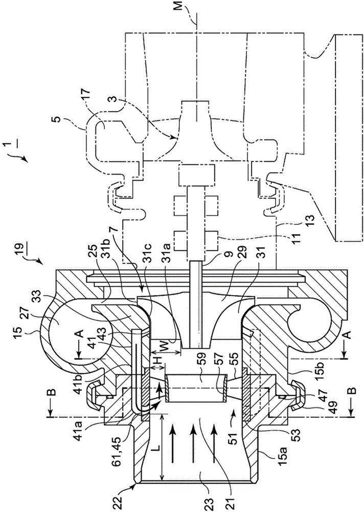
[0081] figure 1 It is a sectional view of main parts showing the direction of the rotation axis of the exhaust turbocharger 1 of the internal combustion engine. The exhaust turbocharger 1 is composed of a turbine housing 5, a bearing housing 13, and a compressor housing 15. The turbine housing 5 accommodates the turbine rotor 3 driven by the exhaust gas of the internal combustion engine. The bearing housing 13 passes through the bearing 11. The rotary shaft 9 that transmits the rotational force of the turbine rotor 3 to the impeller 7 is rotatably supported, and the compressor case 15 accommodates the impeller 7 that sucks and compresses air as intake gas.

[0082] In the outer peripheral portion of the turbine casing 5, a spiral scroll passage 17 is formed on the outer periphery of the turbine rotor 3, and the exhaust gas from the internal combustion engine flows from the outer peripheral side to the shaft center side, and then is discharged in the axial direction to make th...

no. 2 approach

[0134] Next, refer to Figure 5 , 6 A second embodiment will be described.

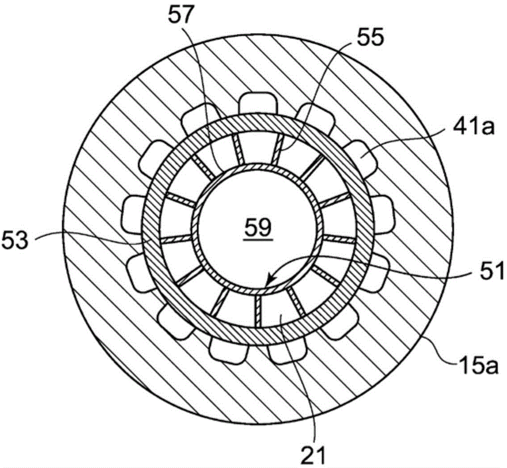
[0135] The recirculation channel 70 of the second embodiment is different in that a cylindrical slit hole 71 is provided instead of the plurality of circulation holes 41a formed in the upstream casing 15a of the first embodiment, and other structures It is the same as the first embodiment.

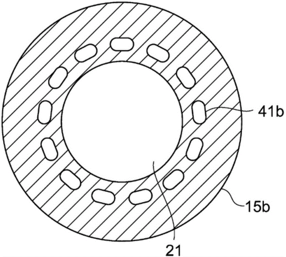
[0136] like Figure 5 , 6 As shown, with respect to the inner peripheral wall of the upstream housing 15a, there is a short diameter side of the oval of the plurality of circulation holes 41b formed in the downstream housing 15b (see figure 2 ), and fits with the outer cylinder member 53 of the swirling flow generating mechanism 51 to form a cylindrical shape formed by the outer peripheral surface of the outer cylinder member 53 and the inner peripheral wall of the upstream housing 15a. The slit void hole 71.

[0137] According to the second embodiment, the recirculation flow path 70 is formed by a single c...

no. 3 approach

[0141] Next, refer to Figure 7 A third embodiment will be described.

[0142] The third embodiment is different in that the shape of the inner peripheral wall of the outer tube member 53 of the swirling flow generating mechanism 51 of the second embodiment is not formed in a cylindrical shape but has a curved shape in the direction of the rotation axis M, and other The structure is the same as that of the second embodiment.

[0143] With respect to the inner peripheral wall of the upstream housing 91, there is a short diameter side of the oval of the plurality of circulation holes 41b formed in the downstream housing 15b (see figure 2 ), the outer cylinder member 95 of the swirling flow generating mechanism 93 is fitted with radial clearances having substantially the same length.

[0144] One substantially cylindrical slit void hole 97 is formed by the outer peripheral surface of the outer cylinder member 95 and the inner peripheral wall of the upstream housing 91 . The r...


PUM


Abstract

An object is to position a plurality of guide vanes for generating swirl flow at a housing inner circumferential side in front of an impeller wheel to improve a surge margin and to restrict the decrease in a choke flow rate, thereby increasing an operation range of a compressor. A compressor 19 includes a compressor housing 15, an impeller wheel 7 which compresses intake gas flowing in from an intake-air inlet 23, a swirl-flow generating part including a plurality of guide vanes 55 disposed circumferentially along an inner circumferential wall of the intake-air channel 21 between the intake-air inlet 23 and the impeller wheel 7 and which swirls the intake gas from the intake-air inlet 23 around the rotational axis, and a central intake-air flow path 59 formed inside the guide vanes 55 to allow intake gas to flow to the impeller wheel 7 without passing through the guide vanes 55.

Description

technical field [0001] The present invention relates to a centrifugal compressor having an impeller rotated by a rotary shaft, and more particularly to a centrifugal compressor incorporated in an exhaust turbocharger. Background technique [0002] In an engine used in a motor vehicle, etc., it is known that in order to increase the output of the engine, the turbine is rotated by the energy of the exhaust gas of the engine, and the intake air is compressed by a centrifugal compressor directly connected to the turbine via the rotating shaft and supplied to the engine. Exhaust turbocharger. [0003] like Figure 11 As shown in the performance characteristics comparison table with the pressure ratio as the vertical axis and the flow rate as the horizontal axis, as shown in the general compressor, the compressor of this exhaust turbocharger is generated by the surge caused by the pulsation of the entire system. The flow rate (the line on the upper left side of the figure) causes...

Claims


Application Information

Patent Timeline
Patent Type & Authority Applications(China)
IPC IPC(8): F04D29/44F04D29/66
CPCF04D29/685F04D29/44F04D29/441F04D29/4213F04D29/66F04D29/444F05D2220/40F02M35/10157F02M35/10262F04D29/681F05D2250/51Y02T10/12F04D17/10
Inventor 安秉一铃木浩
Owner MITSUBISHI HEAVY IND LTD
Why Eureka
Try Eureka