Novel hot-rolled round steel cut-to-length system

A cut-to-length and round steel technology, applied in the field of mechanical engineering, can solve the problems of being easily affected by the external environment during the following process, frequent stop adjustment, poor product adaptability, etc. rate effect

Inactive Publication Date: 2015-03-25
芜湖市海源铜业有限责任公司
View PDF5 Cites 6 Cited by
  • Summary
  • Abstract
  • Description
  • Claims
  • Application Information

AI Technical Summary

Problems solved by technology

[0002] At present, the existing cut-to-length methods for hot-rolled round steel with specifications of φ12mm~φ65mm at home and abroad mainly include fixed-length stop shearing and fixed-length flying shearing. The control of ruler stop and shear is simple, and the precision of length is high. The disadvantage is that the production efficiency is low. For large-scale rolling equipment, frequent start and stop will affect the life of the equipment; currently, the fixed-length flying shears generally use stopper positioning flying shears and servo motors and servo automatic follow-up Flying shears, stopper positioning Flying shears control is relatively simple, it drives the cutting table to follow the flying shears by the profile itself, its disadvantages are frequent stopper adjustments, complex structure, poor product adaptability, and low production efficiency; servo automatically follows the flying shears , the structure of the whole machine is simple, the production line is smooth, and its disadvantages are complex control, high equipment cost, and the following process is easily affected by the external environment
Especially for the cut-to-length hot-rolled round steel with a specification of φ12mm~φ65mm, due to its large diameter, too fast cutting will cause a lot of burrs on the tail of the round steel, and too slow cutting will affect production efficiency, and the required cutting length To be precise, therefore, higher requirements are put forward for the cut-to-length control

Method used


Image

  • Novel hot-rolled round steel cut-to-length system
  • Novel hot-rolled round steel cut-to-length system

Examples


Embodiment Construction

[0024] The present invention will be further described below in conjunction with specific embodiments.

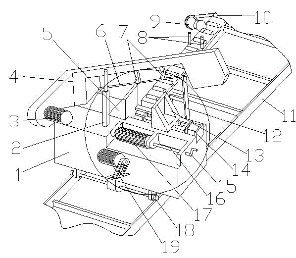
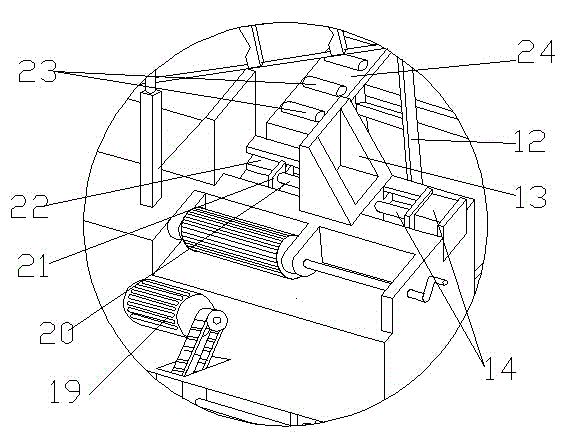
[0025] like figure 1 and figure 2 As shown, a novel hot-rolled round steel fixed-length shearing system includes a feeding car 1, a shear frame 4, a supporting device and a guide rail 8, and the shear frame 4 is hinged on one end of the feeding car 1, and the material The other end of the car 1 is provided with an automatic clamping mechanism and a manual supporting structure. The automatic clamping mechanism includes a first clamping plate 5 and a second clamping plate 13 fixed on the upper end surface of the material truck 1. The end face has a "ten" shaped groove along the front of the first splint 5, the other end of the "cross" shaped groove is fixed with a second hydraulic cylinder 14, and the movable end of the second hydraulic cylinder 14 is connected to the second splint 13 One end of the base is fixedly connected, and the other end surface of the base of the s...


PUM

PropertyMeasurementUnit
widthaaaaaaaaaa

Abstract

The invention discloses a novel hot-rolled round steel cut-to-length system, and belongs to the technical field of mechanical engineering. The novel hot-rolled round steel cut-to-length system comprises a charging skip, a cutting frame, a supporting conveying device and guide rails. The cutting frame is hinged to one end of the charging skip, an automatic clamping mechanism and a manual supporting conveying structure are arranged at the other end of the charging skip, and the automatic clamping mechanism comprises a first clamping plate and a second clamping plate. The supporting conveying device is arranged in the discharging direction of the automatic clamping mechanism and comprises a conveying carrier roller support, a carrier roller base and carrier rollers, and a rotary encoder is installed on the carrier roller base. The cutting frame comprises a cutting saw rotation base, a first driving motor and a transmission device, a cutting saw is arranged at an opening of the cutting saw rotation base and guide wheels are arranged at the lower end of the charging skip and driven by a second motor. The novel hot-rolled round steel cut-to-length system can realize automatic control over fixed-length cutting through the combination of the driving motors, a hydraulic cylinder and the rotary encoder, and through the mobile length fixing mode of a shearing machine, the moving range is small, speed is high, cut-to-length accuracy is high and the working efficiency of the shearing machine can be obviously improved.

Description

technical field [0001] The invention belongs to the technical field of mechanical engineering, and more specifically relates to a novel hot-rolled round steel cut-to-length system. Background technique [0002] At present, the existing cut-to-length methods for hot-rolled round steel with specifications of φ12mm~φ65mm at home and abroad mainly include fixed-length stop-shear and fixed-length flying shear. The efficiency is low. For large-scale rolling equipment, frequent start and stop will affect the life of the equipment; currently, the fixed-length flying shears generally use stopper positioning flying shears, servo motors and servo automatic follow-up flying shears. The control of stopper positioning flying shears is relatively simple. It is determined by the profile The shearing table is driven by itself to follow the flying shears, but its disadvantages are frequent block adjustment, complex structure, poor product adaptability, and low production efficiency; the serv...

Claims


Application Information

Patent Timeline
Patent Type & Authority Applications(China)
IPC IPC(8): B23D25/02B23D33/02B23D33/00
Inventor 钟国伟
Owner 芜湖市海源铜业有限责任公司
Why Eureka
Try Eureka