Clamp for battery laser welding

A battery laser welding, laser welding machine technology, applied in the direction of laser welding equipment, welding equipment, welding equipment, etc., can solve the problems of weak welding, affecting production efficiency, left and right shaking, etc., to prevent the welding from being weak and easy to fall off, The effect of improving welding quality and structural stability

Active Publication Date: 2015-03-25
深圳市电精灵销售有限公司
View PDF13 Cites 31 Cited by
  • Summary
  • Abstract
  • Description
  • Claims
  • Application Information

AI Technical Summary

Problems solved by technology

[0004] 1. There is a deviation in positioning: the fixture uses a quick-turning clamp to press and position. When pressing down, due to the structural defect of the quick-turning clamp itself, it will shake left and right. After pressing down, the pressure claw will deviate from the predetermined position, that is, it cannot be accurate. Positioning at the welding position may cause the pressure claw parts to block the laser spot, resulting in insufficient welding at the welding position between the tab and the PCM board, which will eventually affect the character and quality of the finished battery; 2. Uneven force: the rapid flip clamp of the existing fixture The fixed block on the top is equipped with two pressing claw parts. When pressing down, there is a hidden danger of pressing on one side but there is a gap on the other side, and the welding position between the unpressed

Method used


Image

  • Clamp for battery laser welding
  • Clamp for battery laser welding
  • Clamp for battery laser welding

Examples


Embodiment Construction

[0027] The preferred embodiments of the present invention will be described below in conjunction with the accompanying drawings.

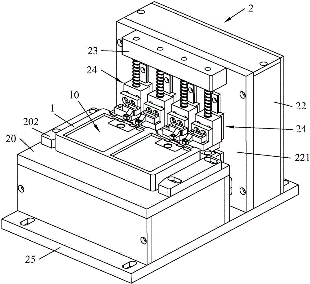
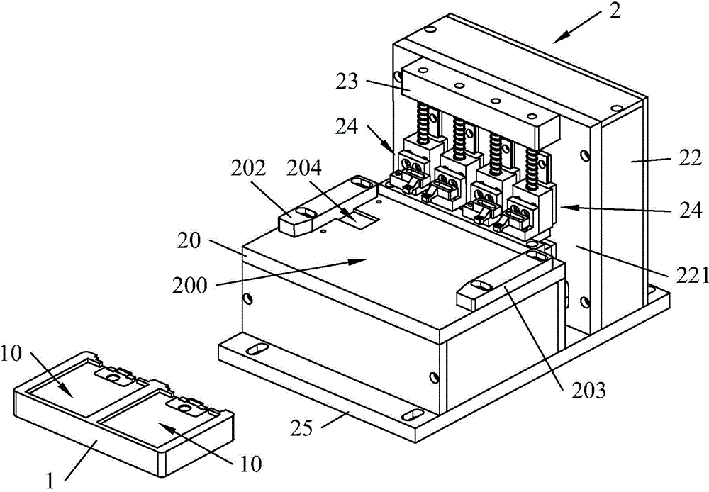
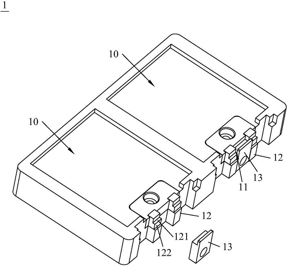
[0028] Such as Figure 1 to Figure 4 and Figure 7As shown, the present invention provides a jig for battery laser welding, including a positioning jig 1 and a jig body 2 fixed on a laser welding machine. The upper end surface of the positioning jig 1 is recessedly formed with at least one positioning groove 10 for accommodating the electric core, one end of the positioning groove 10 is open, and the positioning jig 1 is also provided with a side and accommodate the slot 11 of the PCM board. The clamp body 2 includes a positioning seat 20 , a linear drive device 21 , a mounting plate 221 , a fixing plate 23 and at least two pressing and positioning components 24 . The positioning seat 20, the linear drive device 21 and the mounting plate 221 are fixed to the laser welding machine, the mounting plate 221 stands upward, and the upper end surface o...


PUM


Abstract

The invention discloses a clamp for battery laser welding. The clamp comprises a positioning jig and a clamp body. The positioning jig hollowly forms positioning grooves and clamping positions, wherein the positioning grooves are used for containing battery cores, one end of each positioning groove is opened, and each clamping position is located on the opened side of the corresponding positioning groove and used for containing PCM boards. The clamp body comprises compressing positioning assemblies, a fixing plate, a positioning base, linear driving devices and a mounting plate, wherein the positioning base, the linear driving devices and the mounting plate are fixedly connected with a laser-beam welding machine. The positioning base is provided with a positioning interval used for containing a positioning jig, and the linear driving devices are located between the positioning base and the mounting plate and are provided with output ends which slide up and down. The fixing plate is fixed at the upper end of the mounting plate. Each compressing positioning assembly comprises a mounting base, an elastic piece and a pressing pawl. The mounting bases are arranged on the mounting plate in an up-down sliding mode, the elastic pieces are arranged between the mounting base and the fixing plate, and the pressing pawls are mounted on the mounting base and are provided with butting parts with through holes. In the compressing process of the clamp, only the linear sliding movement is made, positioning is accurate, welding quality and final product performance can be improved, the clamp is divided into two parts, and thus operation is made easier.

Description

technical field [0001] The invention relates to the technical field of fixtures for battery products, in particular to a fixture for laser welding of batteries. Background technique [0002] In the production process of mobile phone batteries, it is necessary to weld the tabs of the battery cell and the PCM board (protection plate). This welding process is one of the most important links in the battery production process, and its welding quality has a great impact on the performance of the final product. In the welding process, it is necessary to use fixtures to position and fix the tabs of the battery cell and the PCM board. [0003] The existing laser welding jig has two grooves for accommodating electric cores formed in a concave manner on its top surface, and the same ends of the two grooves are respectively formed with clamping positions for accommodating PCM boards, and two respectively are installed on the jig. The quick flip clamp corresponding to the two grooves, o...

Claims


Application Information

Patent Timeline
IPC IPC(8): B23K26/70
CPCB23K37/0443
Inventor 刘厚德龚双新刘君雁颜超
Owner 深圳市电精灵销售有限公司
Why Eureka
Try Eureka