Welding method for furnace top flange of blast furnace

A welding method and blast furnace technology, which are applied in welding equipment, arc welding equipment, manufacturing tools, etc., can solve the problems of difficult construction, high welding quality requirements, and excessive levelness of the upper surface of the flange. Welding deformation, the effect of ensuring levelness

Active Publication Date: 2015-03-25
CHINA 19TH METALLURGICAL CORP
View PDF1 Cites 23 Cited by
  • Summary
  • Abstract
  • Description
  • Claims
  • Application Information

AI Technical Summary

Problems solved by technology

During the installation of the blast furnace roof flange, the most difficult thing to control is the welding deformation, because the deformation caused by the welding stress affects the levelness of the upper surface of the furnace roof flange, which may easily cause the levelness of the upper surface of the flange to exceed the standard, which will affect the subsequent construction (such as The installation of furnace top charging equipment) brings great difficulties, so the requirements for welding quality are high

Method used


Image

  • Welding method for furnace top flange of blast furnace
  • Welding method for furnace top flange of blast furnace
  • Welding method for furnace top flange of blast furnace

Examples


Embodiment Construction

[0038] With reference to the attached drawings below, take 3200m 3 The installation of the furnace top flange on the blast furnace project is a specific example, and the specific implementation of the present invention will be further described.

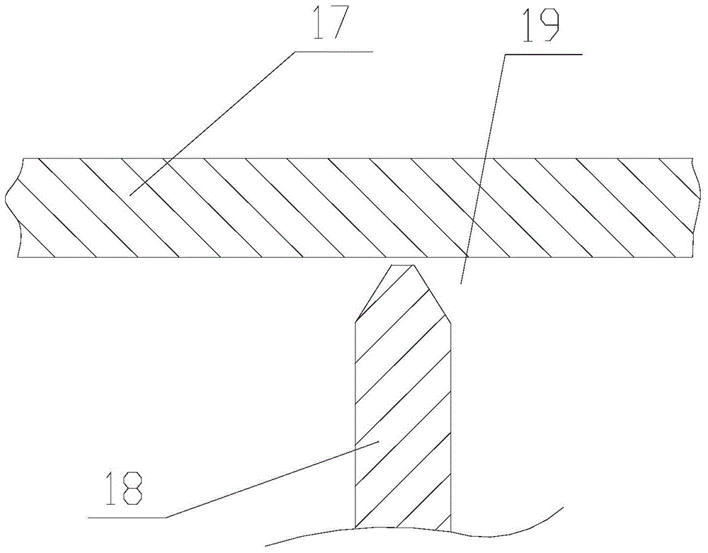
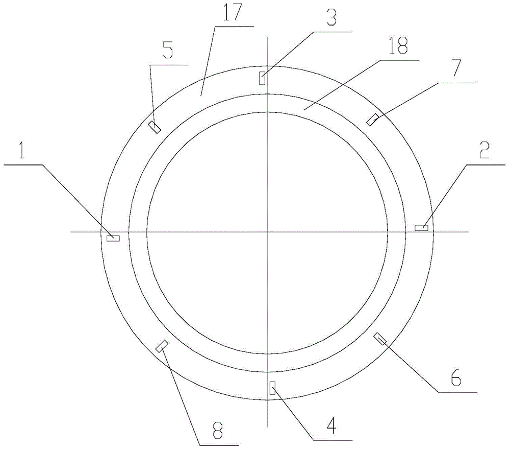
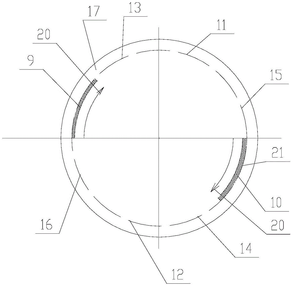
[0039] See figure 1 , figure 2 , image 3 As shown, the elevation of the upper surface of the furnace roof flange is ▽+46.1m, the diameter of the welding seam of the furnace roof flange (the pitch circle between the furnace roof flange and the furnace roof steel ring) is φ3100mm, and the welding seam elevation is ▽+45.6m. The installation requirements are as follows:

[0040]

[0041] Among them: H is the elevation of the furnace top flange; h is the elevation of the furnace bottom; D is the diameter of the weld of the furnace top flange.

[0042] For the installation and welding of the furnace top flange, it is necessary to make preparations before construction.

[0043] Preparations before construction include:

[0044] Prepare the drawin...


PUM


Abstract

The invention discloses a welding method for a furnace top flange of a blast furnace. The method mainly comprises the following steps that checking and accepting; measuring and paying off; groove preparation; hoisting in position; leveling and centering; scale division and marking out, wherein even scale division and marking out are carried out on the furnace top flange through two or more diameter lines, pitch circles of rib plates arranged on the furnace top flange are equally divided into a plurality of small circular arcs, pitch circles, crossing with a furnace top steel ring, of the furnace top flange are equally divided into a plurality of small circular arcs, and pitch circle face, crossing with the furnace top steel ring, of the furnace top flange are equally divided into a plurality of congruent small sectors; rib plate welding, wherein the two sides of the rib plates are fixedly connected from the inner ends to the other ends through a symmetric welding method, and the welding speed is the same; flange welding, wherein backing weld and layered continuous bead welding are included; according to backing weld, the symmetric welding method is adopted, in the manual electric-arc welding manner, same-direction symmetric welding begins to be carried out on two sides of grooves in the centered and segmented symmetric segments at the same time, and according to the layered continuous bead welding, the number of welding layers is determined according to the thickness of the furnace top steel ring and the thickness of the furnace top flange, and the symmetric welding method is adopted, and same-direction continuous bead welding begins to be carried out on the two sides of the grooves in the centered and segmented symmetric segments at the same time.

Description

Technical field [0001] The invention discloses a welding method for the top flange of a blast furnace. Background technique [0002] Furnace roof flange is the most important reference surface for the installation of furnace roof charging equipment. In the process of installing the top flange of the blast furnace, the most difficult to control is the welding deformation, because the deformation caused by welding stress affects the level of the top surface of the top flange, which will easily cause the level of the flange top surface to exceed the standard, which will cause subsequent construction (such as The installation of furnace top loading equipment) brings great difficulties, so the welding quality is required to be high. Summary of the invention [0003] The purpose of the present invention is to provide a welding method for the top flange of a blast furnace. [0004] The purpose of the present invention is achieved through the following technical solutions: [0005] A weldi...

Claims


Application Information

Patent Timeline
Patent Type & Authority Applications(China)
IPC IPC(8): B23K31/02
CPCB23K9/007B23K31/02
Inventor 唐定方
Owner CHINA 19TH METALLURGICAL CORP
Why Eureka
Try Eureka