
hydrostatic pressure release

The technology of hydrostatic pressure and release device is applied in the field of underwater automatic release device, which can solve the problems of complex structure, hidden safety hazards, low assembly efficiency, etc., and achieve the effect of safe transportation process, guaranteeing normal use, and not easy to deform.

Active Publication Date: 2017-01-11
CETC NINGBO MARINE ELECTRONICS RES INST
View PDF6 Cites 0 Cited by
  • Summary
  • Abstract
  • Description
  • Claims
  • Application Information

AI Technical Summary

Problems solved by technology

However, most of the existing hydrostatic pressure release devices are complex in structure, high in cost, and low in assembly efficiency. After installation, the core rod is not only subjected to the top pressure of the top pressure mechanism, but also is subjected to the pulling force of the equipment to be released, such as the shell of the emergency radio position indicator. , On the one hand, it is easy to cause the core rod to deform, and even the core rod cannot be disengaged from the release device smoothly; , the core rod is easy to break away from the release device under the action of external force, so there is a certain potential safety hazard

Method used


Image

  • hydrostatic pressure release
  • hydrostatic pressure release
  • hydrostatic pressure release

Examples


Embodiment Construction

[0015] The present invention will be further described in detail below in conjunction with the accompanying drawings and embodiments.

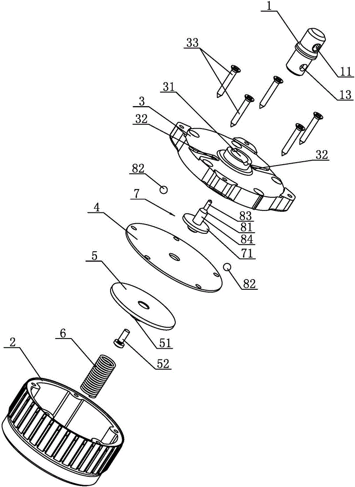
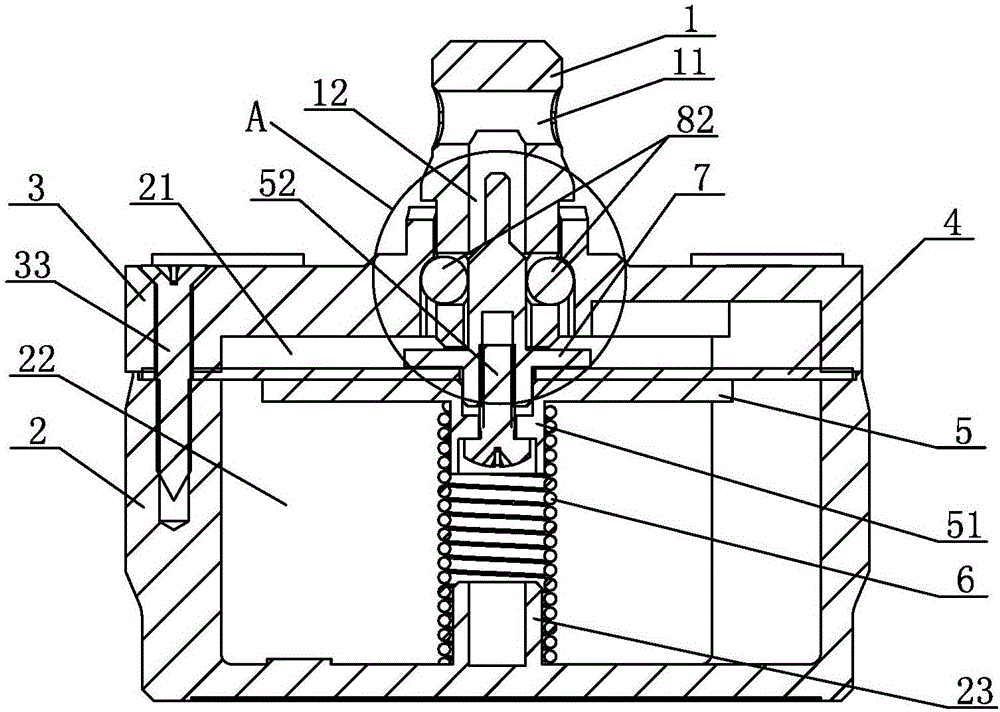
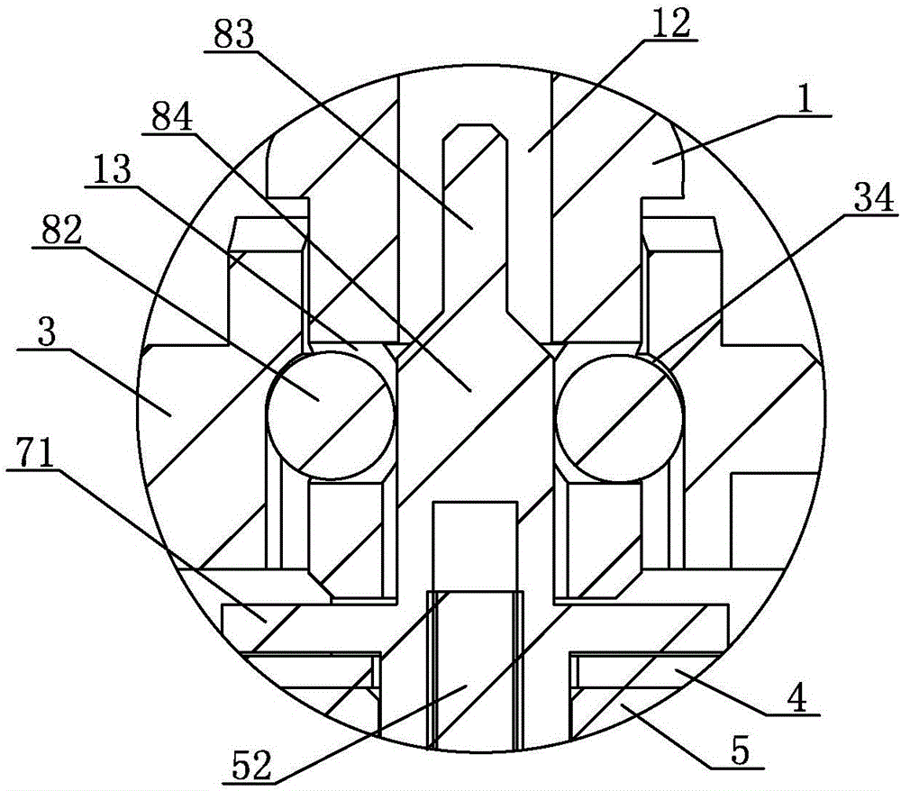
[0016] The hydrostatic pressure release device of the embodiment, as shown in the figure, includes a core rod 1, a base 2 and an end cover 3, the end cover 3 is fixed on the upper part of the base 2, and the end cover 3 is provided with a mounting hole 31 and two symmetrically arranged The water inlet hole 32, the upper end of the core rod 1 is provided with a connection hole 11 for connecting the device to be released (not shown in the figure), the base 2 and the end cover 3 form a chamber, and the end cover 3 and the base 2 are fixed There is a rubber membrane 4, the end cover 3, the rubber membrane 4 and the base 2 are fixedly connected by five connecting screws 33, the rubber membrane 4 divides the chamber into an upper chamber 21 and a lower chamber 22, and the lower part of the rubber membrane 4 is provided with a pressure plate 5. A sup...


PUM


Abstract

The invention discloses a hydrostatic pressure release device. A core bar locking mechanism of the hydrostatic pressure release device comprises a stop pin and two balls; the stop pin is fixed at the upper end of a sliding block; an inner cavity with an opening in the lower part is arranged in a core bar; the core bar sleeves outside the stop pin; the stop pin and the inner cavity are in clearance fit; two symmetrical radial through holes are formed in the side wall of the lower part of the core bar; one ball is installed in each of the two radial through holes; the diameter of each ball is greater than the depth of each radial through hole; the two balls are limited in the two radial through holes through an end cover and the stop pin. The hydrostatic pressure release device disclosed by the invention is convenient to assemble; after the integral structure is installed, the two balls are assembled in the radial through holes in the core bar; then, the core bar is forcefully pressed, so that the core bar and the balls can be assembled in an installation hole together; the core bar in the invention is basically subjected to tensile force of an emergency position-indicating radio beacon shell, so that the core bar is not liable to deformation; furthermore, the core bar is not pulled out easily in non-normal use; therefore, the hydrostatic pressure release device is safer and more reliable in the transportation process; underwater normal use of the hydrostatic pressure release device is ensured.

Description

technical field [0001] The invention relates to an underwater automatic release device, in particular to a hydrostatic pressure releaser. Background technique [0002] At present, the equipment equipped on many ships needs to meet the function of automatic underwater release, such as emergency radio position indicating beacons, marine navigation information recorders, etc., most of which are realized by installing hydrostatic pressure release devices, which are small in size. When the ship sinks in an accident, the release of the equipment can be realized. During installation, the device to be released is connected to the hydrostatic pressure release device through the plastic core rod provided on the hydrostatic pressure release device. When releasing, the core rod is separated from the hydrostatic pressure release device to realize the release of the device. However, most of the existing hydrostatic pressure release devices are complex in structure, high in cost, and low ...

Claims


Application Information

Patent Timeline
Patent Type & Authority Patents(China)
IPC IPC(8): B63B23/70
Inventor 徐永刚陈海民
Owner CETC NINGBO MARINE ELECTRONICS RES INST
Learn More