A segment slowly unloading device

A technology of retarder and retarder, which is applied in the field of segmental retarder unloading device, can solve the problems of crane impact and slow movement, etc., and achieve the effects of long working life, reduced impact and small wear

Inactive Publication Date: 2016-08-24
刘洋
View PDF8 Cites 0 Cited by
  • Summary
  • Abstract
  • Description
  • Claims
  • Application Information

AI Technical Summary

Problems solved by technology

[0005] The hydraulic uncoupling device combines the automatic coupling device and the hydraulic cylinder through the four-bar linkage mechanism, and uses the movement of the piston rod of the cylinder to increase the uncoupling speed, which can solve the problem of slow movement when the mechanism passes the dead point, but the hydraulic uncoupling device relies on the electromagnetic reversing valve for reversing Switch the oil circuit to control the movement of the oil cylinder, the hydraulic pressure in the oil cylinder is released instantly, the tension of the wire rope of the suspension hydraulic decoupler instantly steps to zero, and the large instantaneous jump of the tension of the wire rope brings a violent impact to the crane

Method used


Image

  • A segment slowly unloading device
  • A segment slowly unloading device
  • A segment slowly unloading device

Examples


Embodiment 1

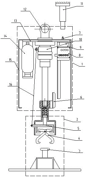
[0041] refer to figure 1 , the subsection retarder unloading device of the present embodiment comprises a retarder 1 and an automatic hooker 2, the automatic hooker 2 is located under the retarder 1, the automatic hooker 2 is connected with the retarder 1, and the retarder 1 A spring contact rod 11 is provided above the top of the retarder 1; a hydraulic oil circuit for controlling the hydraulic pressure of the retarder 1 is provided in the retarder 1.

[0042] The retarder 1 comprises a base 13, the top of the base 13 is provided with a suspension ring 12 and a first switch 7, and the bottom of the base 13 is provided with an accumulator 14, an oil cylinder 10, a storage battery 9, and an oil cylinder all connected to the base 13. A wedge-shaped bumper 6 is arranged below the 10, and the wedge-shaped bumper 6 is connected to the piston rod of the oil cylinder 10; a valve block 8 is arranged below the battery 9, and the first switch 7 is electrically connected to the valve blo...

Embodiment 2

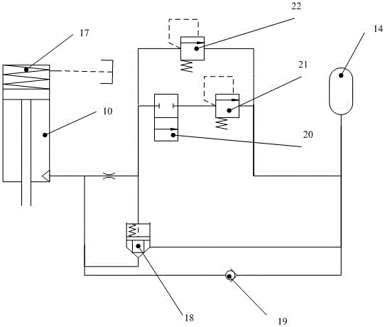
[0059] refer to Figure 4 , the difference between this embodiment and Embodiment 1 is that a switch is provided below the valve block 8, which is the second switch 23; refer to Figure 5 , the number of control oil circuits is two, divided into the first control oil circuit and the second control oil circuit, the second switch 23 is electrically connected with the electromagnetic reversing valve 20 of the second control oil circuit, and is used to control the second control oil circuit The power supply of the electromagnetic reversing valve 20 of the circuit is switched on and off. There are two oil cylinders 10, and the two oil cylinders 10 are connected in parallel. The first switch 7 and the second switch 23 are travel switches. All the other are with embodiment 1.

[0060] When the present embodiment is in use, the steel wire rope is first connected to the suspension ring 12, and then the entire segmented slow-speed unloading device is suspended below the hook of the c...

Embodiment 3

[0066] refer to Figure 7 , the difference between this embodiment and Embodiment 1 is that there are two switches under the valve block 8, which are respectively the second switch 23 and the third switch 24, and the second switch 23 is located above the third switch 24 and located in the same vertical position. In the vertical direction, the vertical length of the wedge-shaped bumper 6 is greater than the distance between the second switch 23 and the third switch 24; refer to Figure 8 , the number of control oil circuits is three, which are divided into the first control oil circuit, the second control oil circuit and the third control oil circuit, and the second switch 23 is electrically connected with the electromagnetic reversing valve 20 of the second control oil circuit for Control the power on and off of the electromagnetic reversing valve 20 of the second control oil circuit; the third switch 24 is electrically connected with the electromagnetic reversing valve 20 of ...


PUM


Abstract

The invention discloses a segmented retardant discharging device. The segmented retardant discharging device comprises an automatic hooking device and a retarder, wherein the automatic hooking device is positioned below the retarder and is connected with the retarder, a spring feeler lever is arranged above the retarder, and the retarder is internally provided with a hydraulic oil path used for controlling hydraulic pressure of the retarder. According to the segmented retardant discharging device disclosed by the invention, by reducing the hydraulic pressure of the retarder in a grading mode, tensile force of a steel wire rope for hanging a heavy hammer is gradually reduced, and the heavy hammer is subjected to putting down in a stair-shaped slow descending mode from a step releasing mode, so that impact to a system due to heavy hammer release is reduced, the rebound of a cargo boom is small, the rope disordering probability of the steel wire rope is low, the abrasion of the automatic hooking device is slight, the whole machine vibration is slight, and the service life is long.

Description

technical field [0001] The invention relates to a segment slow unloading device. Background technique [0002] Impact machinery refers to a sudden change in the state of a mechanical system or a part of it that is suddenly, sharply, and non-periodically excited, which occurs much faster than the natural vibration period of the system, such as continuous wall grabs and dynamic compactors. The dynamic tamping machine relies on the release of the heavy hammer from high altitude to impact the ground, that is, the heavy hammer is raised to a height of tens of meters and released instantaneously. At present, the high-altitude release of the heavy hammer mainly uses a decoupling mechanism. Typical decoupling mechanisms include mechanical decoupling devices, automatic decoupling devices and hydraulic decoupling devices. [0003] The existing mechanical uncoupling device utilizes the self-locking property of the dead point of the mechanism to lift the heavy hammer of tens of tons to...

Claims


Application Information

Patent Timeline
Patent Type & Authority Patents(China)
IPC IPC(8): B66C1/10B66C1/28B66C13/20F15B1/02F15B13/02
CPCB66C1/10B66C1/28B66C13/20F15B1/021F15B13/02
Inventor 刘洋
Owner 刘洋
Why Eureka
Try Eureka